
Yes. They are technically identical documents published under two designations. The current edition is ANSI/NACE MR0175-2021/ISO 15156:2020, fourth edition, described on its own cover as identical to ISO 15156:2020. Copyright is held jointly by AMPP and ISO.

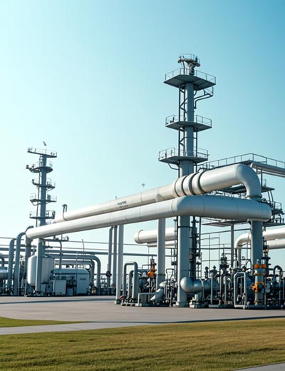
NACE MR0175 / ISO 15156 Standard
Ask for NACE MR0175 material and you will be quoted against ISO 15156. Ask for ISO 15156 and the mill certificate may say ANSI/NACE MR0175-2021. They are the same standard: one technical document, published under two designations by two organisations, in three parts.
The current edition is ANSI/NACE MR0175-2021/ISO 15156:2020, fourth edition, identical to ISO 15156:2020. It was developed on 22 December 2021 by AMPP Standards Committee 08, Metallic Material Selection and Testing, and approved as an American National Standard on 21 September 2022. Copyright is held jointly by AMPP and ISO.
This page explains what the standard covers, how the naming works, what sits in each of the three parts, and which alloys qualify for sour service. Each part has its own detailed page with the full limits, hardness ceilings and Annex A tables — ISO 15156-1, ISO 15156-2 and ISO 15156-3 — and this page is the map that gets you to the right one.
NACE MR0175 / ISO 15156 Free Download NACE MR0175 / ISO 15156 Free Download
NACE MR0175, ISO 15156, AMPP: Which Name Do I Use?
All four designations refer to the same technical document. The differences are about publisher and national adoption, not content. The table shows what each name means and where you will meet it.
| Designation | What It Means | Where You See It |
| NACE MR0175 | The original NACE International designation, first published 1975 | Purchase orders, project specifications, everyday industry speech |
| ISO 15156 | The ISO designation, series completed in 2003 | European and international project specifications |
| NACE MR0175/ISO 15156 | The joint designation used since the 2003 harmonisation | Mill certificates, material test reports |
| ANSI/NACE MR0175-2021/ISO 15156:2020 | The current full designation, ANSI-approved and AMPP-published | The standard document itself |
| AMPP MR0175 | AMPP is the body formed from NACE International and SSPC | Newer AMPP publications and training material |
For procurement, the safe wording names both. A line reading “Material shall comply with NACE MR0175 / ISO 15156-3, Annex A” removes ambiguity about which document and which part the requirement comes from, and tells the mill exactly which tables to certify against.
Where the Standard Came From
Sudden failures of metallic oil and gas field components exposed to H₂S-containing production fluids drove the first edition of NACE MR0175, published in 1975 by the National Association of Corrosion Engineers.
Those early editions established the H₂S partial pressure thresholds above which precautions against sulfide stress cracking were always considered necessary, and gave guidance on selecting SSC-resistant materials once those thresholds were exceeded. Later editions added application limits for corrosion-resistant alloys in terms of environmental composition, pH, temperature and H₂S partial pressure.
Europe developed in parallel. The European Federation of Corrosion issued EFC Publication 16 in 1995 and EFC Publication 17 in 1996, complementary to the NACE documents but differing in scope and detail. In 2003 the ISO 15156 series and NACE MR0175/ISO 15156 were completed for the first time, merging all three sources into one technically identical pair of documents.
Maintenance now runs through a dedicated agency at DIN, set up after ISO Technical Management Board approval in document 34/2007. It includes experts from NACE, EFC and ISO/TC 67. Interim changes are published as Technical Corrigenda or Technical Circulars, which can affect the validity of dated references, so it is worth checking before relying on an older copy.
3 Parts of NACE MR0175 / ISO 15156 and What Each Covers
The standard splits method from material family. Part 1 gives the selection process that applies to every material; Parts 2 and 3 carry the qualified alloy lists for ferrous and corrosion-resistant materials respectively.
| Part | Title | Material Scope | What You Get |
| Part 1 | General principles for selection of cracking-resistant materials | All metallic materials | 7 cracking mechanisms, service condition factors, 3 qualification routes, reporting duties |
| Part 2 | Cracking-resistant carbon and low-alloy steels, and the use of cast irons | Carbon steel, low-alloy steel, cast iron | 4 SSC regions, 22 HRC limit, weld criteria, Annex A steel lists, Annex B test matrix |
| Part 3 | Cracking-resistant CRAs and other alloys | Stainless, duplex, nickel, cobalt, titanium | 13 materials groups, 41 Annex A tables of environmental and metallurgical limits |
You never use Part 2 or Part 3 alone. Part 1 is what tells you which service conditions to document and how to record the selection, and both material parts assume that work has been done first.
Part 1: The Selection Method
Part 1 describes general principles and gives requirements for selecting and qualifying metallic materials for oil and gas production and natural-gas sweetening plants in H₂S environments. It addresses seven cracking mechanisms: SSC, SCC, HIC, SWC, SOHIC, SZC and the newly defined GHSC.
It also sets the three qualification routes (selection from the Annex A lists, documented field experience of at least two years, or laboratory testing) and the rule that qualification transfers only to conditions equal to or less severe in all respects. The ISO 15156-1 standard page covers the equipment scope table, service condition factors and reporting requirements in full.
Part 2: Carbon and Low-Alloy Steels
Part 2 maps H₂S partial pressure against in situ pH into four SSC regions, and the region you land in decides which part of Annex A you may select from. Parent metal baseline caps at 22 HRC; welds baseline cap at 250 HV or 70.6 HR 15N. Exceptions include: up to 275 HV (73.0 HR 15N) for unexposed weld caps (with equipment user agreement and thickness > 9 mm), 187 HBW for ASTM A105 forgings, 197 HBW for ASTM A234 Grade WPB/WPC fittings, and up to 26 HRC or 30 HRC for quenched and tempered Cr-Mo low-alloy steel downhole tubulars and BOP rams.
It covers qualified line pipe, casing, tubing and bolting grades, the cold deformation and stress relief rules, and the separate duty to evaluate flat-rolled products for HIC and SWC at even trace H₂S levels. The ISO 15156-2 standard page sets out the region map, the hardness tables and the Annex B test matrix.
Part 3: Corrosion-Resistant Alloys
Part 3 is the part that matters for stainless, duplex and nickel alloy tubulars. Thirteen materials groups across forty-one Annex A tables give environmental limits for temperature, H₂S partial pressure, chloride concentration and pH, plus the metallurgical condition each alloy must be supplied in.
Duplex is grouped by PREN band rather than grade name, and the PREN limits are absolute values calculated from actual composition. The ISO 15156-3 standard page carries the real Annex A envelopes for 316L, the 6Mo austenitics, duplex, super duplex and the nickel alloy types.
7 Cracking Mechanisms the Standard Addresses
H₂S attacks metal in more than one way, and a material resistant to one mechanism can be vulnerable to another. Part 1 names seven, and the material parts qualify against them separately.
| Mechanism | Abbreviation | Stress Required? | Typical Victim |
| Sulfide stress cracking | SSC | Yes | High-strength steels, hard weld zones |
| Stress corrosion cracking | SCC | Yes | CRAs in chloride plus H₂S at temperature |
| Hydrogen-induced cracking | HIC | No | Steels with planar inclusions and banding |
| Stepwise cracking | SWC | No | Low-strength plate steels for pipe and vessels |
| Stress-oriented HIC | SOHIC | Yes | Longitudinally welded pipe, pressure vessel HAZ |
| Soft-zone cracking | SZC | Yes | Local low-yield zones at carbon steel welds |
| Galvanically induced HSC | GHSC | Yes | Cathode of a galvanic couple |
The 2020/2021 fourth edition introduced three new definitions in Part 1: GHSC (3.14), chemical activity (3.27), and fugacity (3.28). It also introduced normative provisions (Part 1 Clause 6.1 and Part 2 Annex C) permitting the use of H₂S gas fugacity and aqueous chemical activity to evaluate environmental severity in high-pressure systems (> 350 bar / 5,076 psi). GHSC covers cracking from hydrogen induced in the cathode of a galvanic couple plus tensile stress, which is the condition that arises in mixed-metallurgy subsea assemblies and cathodically protected CRA components.
Which Alloys Qualify for Sour Service?
Part 3 qualifies CRAs by materials group, each with its own metallurgical condition, hardness ceiling and environmental envelope. The table gives the headline limits for the families most often specified in sour tubular work.
| Alloy Family | Representative Grades | Max Hardness | Headline Environmental Limit |
| Austenitic stainless | 316L, 317L, 321, 347 | 22 HRC | 316L up to 1,000 kPa H₂S at 60 °C with 50,000 mg/l chloride and in situ pH ≥ 4.5 |
| Highly alloyed austenitic | 904L, 254 SMO, Alloy 926 | Per table | Type 3b to 171 °C at 100 kPa with 5,000 mg/l chloride |
| Duplex stainless | 2205 (S31803, S32205) | Ferrite 35–65 % | 10 kPa (1.5 psi) H₂S at 232 °C, 180,000 mg/l chloride |
| Super duplex stainless | 2507, Zeron 100, S32550 | Ferrite 35–65 % | 20 kPa (3 psi) pH₂S at 232 °C, with no chloride limit set in production environments |
| Solid-solution nickel | 825, 625, C-276, C-22 | No general limit, annealed | No limits on temperature, H₂S, chloride or pH |
| Nickel-copper | Monel 400 | 35 HRC | No environmental limits set |
| Precipitation-hardened nickel | 925, K-500, Alloy 718 | Per table; N07718 40 HRC | Per individual alloy table |
The hierarchy is readable straight off that table. 316L covers mild sour at low temperature, duplex covers high chloride at low H₂S, super duplex doubles the H₂S allowance, and annealed nickel alloys carry no environmental limits at all.
Austenitic Stainless for Mild Sour Duty
316L seamless pipe must be solution-annealed and quenched, free of cold work intended to raise mechanical properties, and held at 22 HRC maximum. Its dedicated Annex A rows reach much further than the generic austenitic envelope, which is why 316L appears in sour specifications more often than its reputation suggests.
6Mo Super-Austenitics for High Chloride
254 SMO seamless pipe qualifies through the PREN above 40.0 route, reaching 171 °C at 100 kPa H₂S with 5,000 mg/l chloride.
904L seamless pipe qualifies as a Type 3a austenitic stainless steel based on composition ((%Ni + 2 × %Mo) > 30 with Mo ≥ 2 %). It is restricted to a maximum temperature of 60 °C (140 °F), a maximum H₂S partial pressure of 100 kPa (15 psi), and maximum chlorides of 50 mg/l under Table A.8 (or 350 kPa pH₂S for downhole tubulars under Table A.9). It does not qualify for the extended Type 3b envelopes (121 °C–171 °C), which strictly require PREN > 40.0.
Duplex and Super Duplex for Strength Plus Chloride
Duplex 2205 seamless pipe sits in the PREN 30 to 40.0 band at 10 kPa H₂S, with 450 MPa (65 ksi) minimum yield and a mandatory 35 % to 65 % ferrite window. Ferrite outside that range disqualifies the material regardless of chemistry.
Super duplex 2507 seamless pipe clears PREN 40.0 and doubles the H₂S allowance to 20 kPa while reaching 550 MPa (80 ksi) minimum yield. That doubled allowance is the clearest commercial reason to step up from standard duplex in sour duty.
Nickel Alloys for Severe and Sulphur-Bearing Service
Incoloy 825 seamless pipe qualifies as a solid-solution nickel alloy in the annealed condition, carrying no limits on temperature, H₂S partial pressure, chloride or pH. Its copper content handles the reducing acid chemistry that attacks duplex.
Inconel 625 seamless pipe sits in the same unrestricted group with 8–10 % molybdenum and 3.15–4.15 % niobium, commonly specified as solid wall for critical components and as clad or overlay on carbon steel for longer runs.
Elemental sulphur narrows the field sharply. Duplex and highly alloyed austenitic rows carry no sulphur-service data or an outright No. Hastelloy C-276 seamless pipe and the other annealed nickel alloys are the ones marked sulphur-resistant.
If you want to know more product details, please contact us!
How to Apply the Standard on a Project
The sequence is fixed and the order matters. Skipping step one makes every later step unverifiable, because the limits in Parts 2 and 3 only mean something against documented service conditions.
- Document the service conditions: H₂S partial pressure, in situ pH, chloride, elemental sulphur, temperature, galvanic effects, stress and wetted time, including upset and shutdown exposures
- Confirm the equipment is in scope: Part 1 Table 1 lists what the standard covers and what it excludes
- Choose the material family: Part 2 for carbon and low-alloy steel, Part 3 for CRAs
- Find the right Annex A table: separate tables exist for general equipment, downhole components and valve stems, and the component-specific ones are often less restrictive
- Match the whole row: temperature, H₂S, chloride and pH must all fall inside one row, read together rather than column by column
- Specify the metallurgical condition: heat treatment, hardness ceiling and, for duplex, the ferrite window
- Qualify welds separately: through Annex A conformance, Annex B testing or documented field experience
- Record the selection: Part 1 Clause 9 sets what the documentation must contain for each qualification route
One rule catches people out repeatedly. Qualification transfers only to conditions equal to or less severe in all respects. A material qualified at 60 °C and 0.3 bar H₂S is not qualified at 80 °C and 0.1 bar, because temperature rose even though H₂S fell.
Who Is Responsible for What
The standard assigns responsibility explicitly, and the split surprises buyers who assume the mill carries it.
| Party | Responsibility |
| Equipment user | Defining, evaluating and documenting service conditions; ensuring any material specified is satisfactory in the service environment; verifying qualifications and retaining supporting documentation |
| Equipment or materials supplier | Meeting the metallurgical and manufacturing requirements; carrying out any additional testing required; conforming with the marking and documentation rules |
| Both parties | Agreeing test and acceptance requirements where Option 2 or Annex B qualification is used, and documenting those agreements |
The warning that opens Part 1 reinforces it. Materials selected using the standard resist cracking in defined H₂S environments but are not necessarily immune to cracking under all service conditions, and selecting material suitable for the intended service is the equipment user’s responsibility.
What the Standard Does Not Cover
Three scope limits are worth knowing before you apply it somewhere it was never meant to go.
Refining and Downstream
Part 1 states the standard is not necessarily applicable to refining or downstream processes and equipment. NACE MR0103 is the companion document for refinery sour service.
Strain-Based Design
The standard applies to equipment designed and constructed using load-controlled design methods. Where strain-based design is used, the equipment user and supplier must agree other test methods and acceptance criteria, because the series does not address them.
Injection and Flowback Chemicals
The Part 3 Annex A tables cover production environments and do not cover conditions during injection or flowback of chemicals that can reduce in situ pH. Stimulation acid backflow needs separate assessment.
Summary
NACE MR0175 and ISO 15156 are one standard in three parts. Part 1 gives the method, Part 2 qualifies carbon and low-alloy steels through four SSC regions and a 22 HRC ceiling, and Part 3 qualifies CRAs through forty-one Annex A tables of environmental limits. Laboratory qualification under any part runs on the test methods in NACE TM0177.
The practical sequence runs the same way every time: document the service conditions, confirm scope, pick the material part, find the right table, match the whole row, specify the metallurgical condition, qualify the welds, record the selection. Compliance is always conditional on the environment the material actually sees.
Frequently Asked Questions
-
Is NACE MR0175 the Same as ISO 15156?
-
What Happened to NACE International?NACE International and SSPC merged to form AMPP, the Association for Materials Protection and Performance, which now publishes the standard. The MR0175 designation was retained, so purchase orders citing NACE MR0175 remain valid and unambiguous.
-
Which Part Do I Need for Stainless Steel Pipe?
-
What Does NACE Compliant Material Mean?It means the material conforms to the metallurgical requirements of the relevant Annex A entry and is being used inside that entry’s environmental limits. Compliance is conditional, not absolute: the same heat of duplex is compliant at 10 kPa H₂S and non-compliant at 30 kPa. A certificate should name the part, the table and the conditions.
-
What H₂S Level Makes a Service Sour?For carbon steel, Part 2 sets the general SSC boundary at 0.3 kPa (0.05 psi) H₂S partial pressure, though flat-rolled products exposed to any H₂S below 0.3 kPa still require HIC/SWC evaluation. For CRAs, while application limits depend on specific material groups, individual tables incorporate discrete lower pH₂S thresholds (such as 3.4 kPa or 10 kPa) to unlock expanded environmental limits.
-
Does the Standard Apply to Refinery Equipment?No. Part 1 states it is not necessarily applicable to equipment used in refining or downstream processes. NACE MR0103 covers refinery sour service. Applying MR0175 to a refinery unit imports limits derived from production conditions that may not match the real exposure.
-
How Often Is the Standard Updated?The fourth edition dates from 2020, replacing the 2015 third edition. Between full editions, interim changes are published as Technical Corrigenda or Technical Circulars through the maintenance agency at DIN. Those interim documents can affect the validity of dated references, so check for them before relying on an older copy.
-
Can I Use a Material Outside Its Annex A Limits?Yes, by qualification. Both Part 2 and Part 3 allow a material to be qualified by laboratory testing for conditions more severe than the Annex A entries give, or for different metallurgical conditions. Documented field experience of at least two years is the third route. All three require documentation to the standard set in Part 1 Clause 9.