
− 196 °C, with steel grade X10Ni9 (1.5682), the 9 % nickel steel. At that temperature, it returns a minimum average 40 J longitudinal and 27 J transverse on three Charpy V-notch test pieces, for wall thickness up to and including 40 mm. No other grade in the standard carries data below − 120 °C.

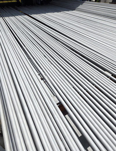
BS EN 10216-4:2013 Standard For Seamless Steel Tubes
BS EN 10216-4:2013 is the European standard for seamless steel tubes for pressure purposes, Part 4: Non-alloy and alloy steel tubes with specified low temperature properties. It is the part of the EN 10216 series specified when the tube has to stay tough below ambient, and it is the only part in the series that carries verified impact data down to − 196 °C.
The standard was approved by CEN on 17 August 2013 and supersedes EN 10216-4:2002. It was prepared by Technical Committee ECISS/TC 110, Steel tubes and fittings for steel tubes, with the secretariat held by UNI, and it supports the Essential Requirements of the Pressure Equipment Directive 97/23/EC through Annex ZA.
Part 4 covers nine steel grades arranged as a temperature ladder: three non-alloy quality steels reaching − 40 °C, or − 50 °C for P255QL in thinner wall, a chromium-molybdenum grade and two manganese-nickel grades reaching − 60 °C, and three nickel steels - 3,5 %, 5 % and 9 % nickel - that carry the standard down through − 100 °C and − 120 °C to − 196 °C. Grade selection under this standard is a toughness decision before it is a strength decision. This guide covers the grades, test categories, heat treatment, chemical composition, room temperature and impact properties, dimensional tolerances, inspection and testing, the 14 options, marking, applications and FAQs.
BS EN 10216-4:2013 Free Download BS EN 10216-4:2013 Free Download
What is BS EN 10216-4:2013?
BS EN 10216-4:2013 specifies the technical delivery conditions, in two test categories, for seamless tubes of circular cross section with specified low temperature properties, made of non-alloy and alloy steel. Everything in the standard is built around one property: minimum average Charpy V-notch impact energy at a defined sub-zero temperature.
The standard was prepared under a mandate given to CEN by the European Commission and EFTA. Annex ZA maps its clauses to the Essential Requirements of Directive 97/23/EC:
| Clauses of this EN | Essential Requirement (97/23/EC) | Qualifying Remarks |
| 8.3 | Annex I, 4.1a | Appropriate material properties |
| 7.1 and 8.2 | Annex I, 4.1c | Ageing |
| 7.2 and 8.4 | Annex I, 4.1d | Suitable for the processing procedures |
| 9 and 10 | Annex I, 4.3 | Documentation |
The scope note limits what that presumption of conformity covers. Once the standard is cited in the Official Journal of the European Union under Directive 97/23/EC and has been implemented as a national standard in at least one Member State, compliance with the clauses listed in Table ZA.1 confers a presumption of conformity with the corresponding Essential Safety Requirements (ESR), within the limits of the scope of the standard. The Scope note adds that this presumption is limited to the technical data of the materials in the standard and does not presume adequacy of the material for a specific item of equipment. The designer or manufacturer of the pressure equipment has to assess that data against the design requirements of the specific item, taking into account subsequent manufacturing processes that may affect base material properties.
The general technical delivery requirements of EN 10021 apply in addition. Tubes shall be suitable for hot and cold bending provided the bending is carried out in an appropriate manner. National standards organisations in 33 European countries are bound to implement the standard, and conflicting national standards were to be withdrawn by June 2014.
The EN 10216 Series: Five Parts Explained
EN 10216 is published in five parts under the general title "Seamless steel tubes for pressure purposes - Technical delivery conditions". Selecting the wrong part is the most common specification error with this series, because four of the five parts cover overlapping material families and are separated by service condition.
| Standard | Scope | Selection Basis |
| EN 10216-1 | Non-alloy steel tubes with specified room temperature properties | Room temperature service |
| EN 10216-2 | Non-alloy and alloy steel tubes with specified elevated temperature properties | Elevated temperature service |
| EN 10216-3 | Alloy fine grain steel tubes | Steel type - high strength, weldable, fine grained |
| EN 10216-4 | Non-alloy and alloy steel tubes with specified low temperature properties | Low temperature service |
| EN 10216-5 | Stainless steel tubes | Corrosion resistance |
The parallel series for welded product is EN 10217, Welded steel tubes for pressure purposes - Technical delivery conditions. Part 3 also offers low temperature qualities in its NL and QL grades, and the two parts overlap around − 50 °C. The distinction is range and material: Part 3 stops at − 50 °C in alloy fine grain steels reaching 690 MPa yield. Part 4 carries a short option list: 14 options in total. The options Part 4 does not have are as informative as the ones it does: there is no option for alternative dimension sets, none for elevated temperature verification, and none for impact testing at an additional temperature.
Test Category 1 vs Test Category 2
The test category indicates the extent and level of inspection and testing. It is mandatory order information for non-alloy steel, and it appears in the tube marking for those grades.
Non-alloy steel tubes are inspected and tested to test category 1 or test category 2 as specified at the time of enquiry and order. Alloyed steel tubes are inspected and tested to test category 2 only. Since only three of the nine grades in this standard are non-alloy quality steels, test category 1 is available on a minority of the range.
| Parameter | Test Category 1 (TC1) | Test Category 2 (TC2) |
| Eligible grades | Non-alloy only: P215NL, P255QL, P265NL | All grades; mandatory for every alloy steel grade |
| Type of inspection | Specific inspection | Specific inspection |
| Sample tubes per test unit | One | Two (one where the test unit holds fewer than 20 tubes) |
| NDT for longitudinal imperfections | Not applicable | Mandatory on each tube |
| NDT for transverse imperfections (Option 5) | Not applicable | Available on each tube |
| NDT for laminar imperfections (Option 6) | Not applicable | Available on each tube |
| Cast analysis | One per cast | One per cast |
| Impact test at low temperature | One per sample tube | One per sample tube |
| Leak tightness inspection | Each tube | Each tube |
| Material identification of alloy steel | Each tube | Each tube |
| Marking | Test category shown for non-alloy grades | Test category shown for non-alloy grades |
BS EN 10216-4:2013 Steel Grades
Under the classification system of EN 10020, the grades P215NL, P255QL and P265NL are classified as non-alloy quality steels. The other six grades are classified as alloy special steels.
Designation follows two different rules depending on which group the grade belongs to. Non-alloy steel names are built from the capital letter P for pressure purposes, the specified minimum yield strength at room temperature in MPa, the symbol of the heat treatment, and the symbol L for low temperature - so P265NL reads as a pressure-purpose steel, 265 MPa minimum yield, normalised, low temperature. Alloy steel names are built from the chemical composition plus the heat treatment symbols, which is why 12Ni14 and X10Ni9 carry no P prefix and no yield figure in the name.
| Steel Name | Steel Number | Classification | Heat Treatment | Min Yield | Tensile Rm | Lowest Test Temperature |
| P215NL | 1.0451 | Non-alloy quality | +N | 215 MPa (T ≤ 10 mm) | 360 to 480 MPa | − 40 °C |
| P255QL | 1.0452 | Non-alloy quality | +QT | 255 MPa | 360 to 490 MPa | − 50 °C |
| P265NL | 1.0453 | Non-alloy quality | +N | 265 MPa (T ≤ 25 mm) | 410 to 570 MPa | − 40 °C |
| 26CrMo4-2 | 1.7219 | Alloy special | +QT | 440 MPa | 560 to 740 MPa | − 60 °C |
| 11MnNi5-3 | 1.6212 | Alloy special | +N | 285 MPa | 410 to 530 MPa | − 60 °C |
| 13MnNi6-3 | 1.6217 | Alloy special | +N | 355 MPa | 490 to 610 MPa | − 60 °C |
| 12Ni14 | 1.5637 | Alloy special | +NT or +QT | 345 MPa | 440 to 620 MPa | − 100 °C |
| X12Ni5 | 1.5680 | Alloy special | +NT or +QT | 390 MPa | 510 to 710 MPa | − 120 °C |
| X10Ni9 | 1.5682 | Alloy special | +N+NT or +QT | 510 MPa | 690 to 840 MPa | − 196 °C |
Minimum yield and tensile values apply for wall thickness up to and including 40 mm. The lowest test temperature column is the temperature at which the mandatory impact test is carried out under Clause 11.7.1, for the thinner of the two wall bands where a grade has two.
P215NL, P255QL and P265NL (Non-Alloy Quality Steels)
These three are the entry point of the standard and the only grades that can be ordered to test category 1. P215NL is the softest at 215 MPa minimum yield and is impact tested in the longitudinal direction only, with the standard tabulating properties for wall thickness up to 10 mm. P255QL is the odd one out among the non-alloy grades: it is supplied quenched and tempered rather than normalised, and that heat treatment buys it a − 50 °C test temperature where the normalised P265NL stops at − 40 °C despite the higher yield strength.
26CrMo4-2, 11MnNi5-3 and 13MnNi6-3 (Alloy Grades to − 60 °C)
26CrMo4-2 is the strongest grade in the standard below the nickel steels, at 440 MPa minimum yield and 560 to 740 MPa tensile, achieved through 0,22 to 0,29 % carbon, 0,90 to 1,20 % chromium and 0,15 to 0,30 % molybdenum in the quenched and tempered condition. 11MnNi5-3 and 13MnNi6-3 take a different route to the same − 60 °C: modest carbon, manganese to 1,50 % and 1,70 % respectively, and nickel of 0,30 to 0,80 % and 0,30 to 0,85 % respectively, supplied normalised. The two manganese-nickel grades share a single row in the impact table, so they are specified interchangeably on toughness and separated on strength.
12Ni14, X12Ni5 and X10Ni9 (Nickel Steels for Cryogenic Service)
The three nickel steels are what make Part 4 distinctive. Nickel content rises from 3,25 to 3,75 % in 12Ni14, to 4,5 to 5,3 % in X12Ni5, to 8,5 to 9,5 % in X10Ni9, and the lowest test temperature falls with it - from − 100 °C to − 120 °C to − 196 °C. All three carry a tighter sulfur limit of 0,005 % than the rest of the standard, because sulfide inclusions are what initiate cleavage fracture at cryogenic temperature.
X10Ni9 is the endpoint of the series. At − 196 °C, the boiling point of nitrogen at atmospheric pressure, it still returns 40 J longitudinal and 27 J transverse, and it combines that with the highest strength in the standard at 510 MPa minimum yield and 690 to 840 MPa tensile. It is also the only grade offered in a +N+NT condition, a double heat treatment.
Manufacturing and Heat Treatment Conditions
All tubes are manufactured by a seamless process. Unless Option 1 is specified, the tubes may be either hot or cold finished at the manufacturer's discretion; the terms refer to the condition of the tube before heat treatment. Option 1 requires the tubes to be cold finished before heat treatment. Tubes are then supplied in the heat treatment condition specified in Table 1 for the grade concerned.
| Steel Name | Heat Treatment | Normalising / Hardening Temperature | Cooling Medium | Tempering Temperature |
| P215NL | +N | 900 to 940 °C | - | - |
| P255QL | +QT | 890 to 930 °C | Water or oil | 600 to 680 °C |
| P265NL | +N | 880 to 940 °C | - | - |
| 26CrMo4-2 | +QT | 830 to 860 °C | Water or oil | 600 to 680 °C |
| 11MnNi5-3 | +N | 890 to 940 °C | - | (580 to 640 °C) |
| 13MnNi6-3 | +N | 890 to 940 °C | - | (580 to 640 °C) |
| 12Ni14 | +NT | 830 to 880 °C | - | 580 to 640 °C |
| 12Ni14 | +QT | 820 to 880 °C | Water or oil | 580 to 660 °C |
| X12Ni5 | +NT | 800 to 850 °C | - | 580 to 640 °C |
| X12Ni5 | +QT | 800 to 850 °C | Water or oil | 580 to 660 °C |
| X10Ni9 | +N+NT | 880 to 915 °C + 775 to 805 °C | - | 565 to 605 °C (still air or accelerated cooling) |
| X10Ni9 | +QT | 770 to 820 °C | Water or oil | 540 to 600 °C |
Where the delivery condition is +QT, the temperature shown is the hardening temperature; where it is +N or +NT, it is the normalising temperature.
Six footnotes qualify that table, and three of them change what a purchaser receives. Where two types of heat treatment are specified for a grade, the choice depends on wall thickness and T/D ratio; the decision rests with the manufacturer but has to be reported in the inspection document. For 11MnNi5-3 and 13MnNi6-3, tempering can occasionally be necessary after normalising - the decision again rests with the manufacturer but has to be stated to the customer at enquiry and order, and tubes treated that way are designated by the steel name supplemented by "+NT". For X10Ni9 in the +QT condition, an additional prenormalizing treatment in the range 880 to 930 °C may be necessary, and the manufacturer then has to inform the purchaser.
On the cooling medium, the standard notes that the influence of other parameters such as dimensions and quenching temperature on properties and crack susceptibility should be taken into account, and that other cooling media such as synthetic quenchants may also be used.
The steelmaking process is at the manufacturer's discretion with one exception: the open hearth (Siemens-Martin) process shall not be employed unless combined with a secondary steelmaking or ladle refining process. Steels shall be fully killed, which excludes rimming, balanced and semi-killed steel.
All NDT activities are carried out by qualified and competent level 1, 2 or 3 personnel authorised to operate by the employer, with qualification in accordance with ISO 11484 or at least an equivalent. The standard recommends that level 3 personnel be certified in accordance with EN ISO 9712 or at least an equivalent, the operating authorisation follows a written procedure, and NDT operations are authorised by a level 3 individual approved by the employer.
Chemical Composition of BS EN 10216-4:2013
Chemical composition is specified as cast analysis in Table 2, expressed in % by mass. The cast analysis reported by the steel producer applies. Elements not included in the table shall not be intentionally added without the agreement of the purchaser, except for elements which may be added for finishing the cast. All appropriate measures shall be taken to prevent the addition of undesirable elements from scrap or other materials used in the steelmaking process.
| Steel Name | C | Si | Mn | P max | S max | Cr | Ni | Mo |
| P215NL | ≤ 0,15 | ≤ 0,35 | 0,40 to 1,20 | 0,025 | 0,010 | ≤ 0,30 | ≤ 0,30 | ≤ 0,08 |
| P255QL | ≤ 0,17 | ≤ 0,35 | 0,40 to 1,20 | 0,025 | 0,010 | ≤ 0,30 | ≤ 0,30 | ≤ 0,08 |
| P265NL | ≤ 0,20 | ≤ 0,40 | 0,60 to 1,40 | 0,025 | 0,010 | ≤ 0,30 | ≤ 0,30 | ≤ 0,08 |
| 26CrMo4-2 | 0,22 to 0,29 | ≤ 0,35 | 0,50 to 0,80 | 0,025 | 0,010 | 0,90 to 1,20 | - | 0,15 to 0,30 |
| 11MnNi5-3 | ≤ 0,14 | ≤ 0,50 | 0,70 to 1,50 | 0,025 | 0,010 | - | 0,30 to 0,80 | - |
| 13MnNi6-3 | ≤ 0,16 | ≤ 0,50 | 0,85 to 1,70 | 0,025 | 0,010 | - | 0,30 to 0,85 | - |
| 12Ni14 | ≤ 0,15 | 0,15 to 0,35 | 0,30 to 0,80 | 0,025 | 0,005 | - | 3,25 to 3,75 | - |
| X12Ni5 | ≤ 0,15 | ≤ 0,35 | 0,30 to 0,80 | 0,020 | 0,005 | - | 4,5 to 5,3 | - |
| X10Ni9 | ≤ 0,13 | 0,15 to 0,35 | 0,30 to 0,80 | 0,020 | 0,005 | - | 8,5 to 9,5 | ≤ 0,10 |
| Steel Name | Al total min | Cu max | Nb max | Ti max | V max |
| P215NL, P255QL, P265NL | 0,020 | 0,30 | 0,010 | 0,040 | 0,02 |
| 26CrMo4-2 | - | 0,30 | - | - | - |
| 11MnNi5-3, 13MnNi6-3 | 0,020 | 0,30 | 0,05 | - | 0,05 |
| 12Ni14, X12Ni5, X10Ni9 | - | 0,30 | - | - | 0,05 |
Four footnotes qualify the composition table. Aluminium may be replaced by other elements having a similar effect, by agreement between purchaser and manufacturer. Option 2 allows an agreed maximum copper content lower than tabulated, together with an agreed maximum tin content, to facilitate subsequent forming operations. And for 11MnNi5-3 and 13MnNi6-3, the lower limit for nickel may be reduced to not less than 0,15 % for tubes with wall thickness not exceeding 10 mm.
The sulfur limits are the clearest signal of what this standard is for. The six grades rated to − 60 °C and above hold sulfur at 0,010 % maximum; the three nickel steels rated to − 100 °C and below halve that to 0,005 %. Phosphorus follows the same pattern, tightening from 0,025 % to 0,020 % for X12Ni5 and X10Ni9.
Product Analysis Deviations (Option 3)
Option 3 calls for a product analysis. Table 3 gives the permissible deviations from the cast analysis limits of Table 2. The nickel row is banded four ways, reflecting the wide nickel range the standard covers.
| Element | Cast Analysis Limit (%) | Permissible Deviation (%) |
| C | ≤ 0,29 | ± 0,02 |
| Si | ≤ 0,40 / > 0,40 to 0,50 | ± 0,05 / + 0,06 |
| Mn | ≤ 1,70 | + 0,10 / − 0,05 |
| P | ≤ 0,025 | + 0,005 |
| S | ≤ 0,015 / > 0,015 to ≤ 0,020 | + 0,003 / + 0,005 |
| Al | ≥ 0,020 | − 0,005 |
| Cr | ≤ 1,20 | ± 0,10 |
| Cu | ≤ 0,30 | + 0,05 |
| Mo | ≤ 0,30 | ± 0,05 |
| Nb | ≤ 0,05 | + 0,005 |
| Ni | ≤ 0,85 / > 0,85 to ≤ 3,75 / > 3,75 to ≤ 5,3 / > 5,3 to ≤ 9,5 | ± 0,05 / ± 0,07 / ± 0,10 / ± 0,15 |
| Ti | ≤ 0,040 | + 0,01 |
| V | ≤ 0,05 | + 0,01 |
Mechanical Properties of BS EN 10216-4:2013
Mechanical properties apply irrespective of whether they are verified on the order or not. Unlike Parts 2 and 3, Part 4 does not band yield strength across many wall thickness groups: Table 4 gives a single set of values for wall thickness up to and including 40 mm, which is also the upper limit of the standard's preferred dimensions.
Room Temperature Tensile Properties
| Steel Name | Steel Number | Min Yield ReH or Rp0,2 | Tensile Strength Rm | Elong. Long. | Elong. Trans. |
| P215NL | 1.0451 | 215 MPa (for wall thickness ≤ 10 mm) | 360 to 480 MPa | 25 % | 23 % |
| P255QL | 1.0452 | 255 MPa | 360 to 490 MPa | 23 % | 21 % |
| P265NL | 1.0453 | 265 MPa (for wall thickness ≤ 25 mm) | 410 to 570 MPa | 24 % | 22 % |
| 26CrMo4-2 | 1.7219 | 440 MPa | 560 to 740 MPa | 18 % | 16 % |
| 11MnNi5-3 | 1.6212 | 285 MPa | 410 to 530 MPa | 24 % | 22 % |
| 13MnNi6-3 | 1.6217 | 355 MPa | 490 to 610 MPa | 22 % | 20 % |
| 12Ni14 | 1.5637 | 345 MPa | 440 to 620 MPa | 22 % | 20 % |
| X12Ni5 | 1.5680 | 390 MPa | 510 to 710 MPa | 21 % | 19 % |
| X10Ni9 | 1.5682 | 510 MPa | 690 to 840 MPa | 20 % | 18 % |
Two of the three non-alloy grades carry a thickness qualification on the yield figure: 215 MPa applies to P215NL for wall thickness up to and including 10 mm, and 265 MPa applies to P265NL for wall thickness up to and including 25 mm. Tensile strength is given as a range in every case, and the upper limit is a requirement in its own right - a tube testing above it does not conform, because excess strength compromises the toughness the standard exists to guarantee.
Impact Properties
Table 5 is the substance of Part 4. Minimum average absorbed energy KV2 is tabulated by grade, wall thickness and orientation, across ten test temperatures from + 20 °C down to − 196 °C. Clause 11.7.1 requires the impact test to be carried out at the lowest temperature specified in Table 5 for the steel grade concerned, so the table is not a menu - it fixes the mandatory test temperature grade by grade.
Longitudinal minimum average impact energy KV2 in joules:
| Steel Grade | Wall | − 196 | − 120 | − 110 | − 100 | − 90 | − 60 | − 50 | − 40 | − 20 | + 20 |
| P215NL | ≤ 10 | - | - | - | - | - | - | - | 40 | 45 | 55 |
| P255QL | ≤ 25 | - | - | - | - | - | - | 40 | 45 | 50 | 60 |
| P255QL | > 25 to 40 | - | - | - | - | - | - | - | 40 | 45 | 55 |
| P265NL | ≤ 25 | - | - | - | - | - | - | - | 40 | 45 | 50 |
| 26CrMo4-2 | ≤ 40 | - | - | - | - | - | 40 | 40 | 45 | 50 | 60 |
| 11MnNi5-3, 13MnNi6-3 | ≤ 40 | - | - | - | - | - | 40 | 45 | 50 | 55 | 70 |
| 12Ni14 | ≤ 25 | - | - | - | 40 | 45 | 50 | 55 | 55 | 60 | 65 |
| 12Ni14 | > 25 to 40 | - | - | - | - | 40 | 45 | 50 | 50 | 55 | 65 |
| X12Ni5 | ≤ 25 | - | 40 | 45 | 50 | 55 | 65 | 65 | 65 | 70 | 70 |
| X12Ni5 | > 25 to 40 | - | - | 40 | 45 | 50 | 60 | 65 | 65 | 65 | 70 |
| X10Ni9 | ≤ 40 | 40 | 50 | 50 | 60 | 60 | 70 | 70 | 70 | 70 | 70 |
Transverse minimum average impact energy KV2 in joules. P215NL does not appear below: it is the only grade in the standard for which Table 5 specifies longitudinal test pieces alone, with no transverse requirement.
| Steel Grade | Wall | − 196 | − 120 | − 110 | − 100 | − 90 | − 60 | − 50 | − 40 | − 20 | + 20 |
| P255QL | ≤ 25 | - | - | - | - | - | - | 27 | 30 | 35 | 40 |
| P255QL | > 25 to 40 | - | - | - | - | - | - | - | 27 | 30 | 35 |
| P265NL | ≤ 25 | - | - | - | - | - | - | - | 27 | 30 | 35 |
| 26CrMo4-2 | ≤ 40 | - | - | - | - | - | 27 | 27 | 30 | 35 | 40 |
| 11MnNi5-3, 13MnNi6-3 | ≤ 40 | - | - | - | - | - | 27 | 30 | 35 | 40 | 45 |
| 12Ni14 | ≤ 25 | - | - | - | 27 | 30 | 35 | 35 | 40 | 45 | 45 |
| 12Ni14 | > 25 to 40 | - | - | - | - | 27 | 30 | 30 | 35 | 40 | 45 |
| X12Ni5 | ≤ 25 | - | 27 | 30 | 30 | 35 | 45 | 45 | 45 | 50 | 50 |
| X12Ni5 | > 25 to 40 | - | - | 27 | 30 | 30 | 40 | 45 | 45 | 45 | 50 |
| X10Ni9 | ≤ 40 | 27 | 35 | 35 | 40 | 40 | 50 | 50 | 50 | 50 | 50 |
Reading the tables by column rather than by row shows the design intent. At the lowest temperature each grade is qualified for, the requirement is the same 40 J longitudinal and 27 J transverse - the same numbers for P215NL at − 40 °C and for X10Ni9 at − 196 °C. What alloying buys is not a higher energy value, but the ability to hold that value at a lower temperature.
Wall thickness matters as much as grade. Where a grade has two wall bands, the thicker band loses one temperature step: 12Ni14 is tested at − 100 °C up to 25 mm wall but only − 90 °C above it, and X12Ni5 drops from − 120 °C to − 110 °C the same way. P255QL loses its transverse requirement at − 50 °C entirely once wall exceeds 25 mm.
Specimen and acceptance rules follow the series convention. Three standard Charpy V-notch test pieces are prepared to EN ISO 148-1; where standard 10 mm pieces cannot be produced without flattening, test pieces of width less than 10 mm but not less than 5 mm are prepared, and the largest obtainable width shall be used. Where the width W is less than 10 mm, the measured energy KVp is converted to KVc = 10 × KVp / W; where 5 mm cannot be obtained, the tubes are not impact tested. Test pieces are taken transverse to the tube axis unless Dmin, calculated as (T − 5) + 756,25 / (T − 5), is greater than the specified outside diameter, in which case longitudinal pieces are used.
The mean of three test pieces has to meet the specified value, and one individual value may fall below it provided it is not less than 70 % of that value. If that fails, a second set of three test pieces may be taken from the same sample at the discretion of the manufacturer; the unit then conforms only if the average of all six meets the minimum, no more than two of the six fall below the minimum, and no more than one of the six falls below 70 % of it.
Dimensions, Masses and Tolerances
Tubes are delivered by outside diameter D and wall thickness T. Part 4 offers no option to order by inside diameter or minimum wall thickness, which is a real difference from Parts 2 and 3 and means there are no calculated Dc, dc or Tc values to work with.
Preferred dimensions are selected from EN 10220 and given in Table 6, covering outside diameters from 10,2 mm to 711 mm and wall thicknesses from 1,6 mm to 40 mm. Dimensions different from those in Table 6 may be agreed. The 40 mm wall ceiling matches Table 4, which tabulates mechanical properties for wall thickness up to and including 40 mm, and Table 5, whose thickest band also stops at 40 mm.
Table 6 sorts diameters into three series: series 1 covers diameters for which all the accessories needed to build a piping system are standardised, series 2 those for which not all accessories are standardised, and series 3 special-application diameters for which very few standardised accessories exist. Mass per unit length follows EN 10220, with no grade-specific density corrections.
Tolerances on Diameter and Wall Thickness
Out of roundness is included in the tolerances on diameter and eccentricity is included in the tolerances on wall thickness. Part 4 has only two tolerance tables, one for standard delivery and one for cold finished tube.
| Ordered As | Outside Diameter D | Tolerance on D | T/D ≤ 0,025 | > 0,025 to 0,050 | > 0,050 to 0,10 | > 0,10 |
| Standard (Table 7) | D ≤ 219,1 mm | ± 1 % or ± 0,5 mm, greater | ± 12,5 % or ± 0,4 mm, greater | ± 12,5 % or ± 0,4 mm, greater | ± 12,5 % or ± 0,4 mm, greater | ± 12,5 % or ± 0,4 mm, greater |
| Standard (Table 7) | D > 219,1 mm | ± 1 % or ± 0,5 mm, greater | ± 20 % | ± 15 % | ± 12,5 % | ± 10 % |
| Cold finished (Table 8) | Any | ± 0,5 % or ± 0,3 mm, greater | ± 10 % or ± 0,2 mm, greater | ± 10 % or ± 0,2 mm, greater | ± 10 % or ± 0,2 mm, greater | ± 10 % or ± 0,2 mm, greater |
For outside diameters D ≥ 355,6 mm, Table 7 permits the upper wall thickness to be exceeded locally by a further 5 % of the wall thickness T, in the highest thickness-ratio band. Cold finished tube to Table 8 is roughly twice as tight on diameter and holds ± 10 % on wall regardless of T/D ratio, with no local over-run allowance.
Lengths, Straightness and End Preparation
Unless Option 8 is specified, tubes are delivered in random length, with the delivery range agreed at the time of enquiry and order. Option 8 calls for exact lengths:
| Length L | Tolerance on Exact Length |
| L ≤ 6 000 mm | + 10 mm / 0 |
| 6 000 < L ≤ 12 000 mm | + 15 mm / 0 |
| L > 12 000 mm | + by agreement / 0 |
Deviation from straightness shall not exceed 0,0015 L over any tube length L, and deviation over any one metre length shall not exceed 3 mm.
Tubes are delivered with square cut ends, free from excessive burrs. Option 7 calls for bevelled ends: a bevel angle of 30° (+ 5° / − 0°) with a root face of 1,6 mm ± 0,8 mm, except that for wall thickness greater than 20 mm an alternative bevel may be specified. Unlike Part 3, Part 4 sets no minimum wall thickness for the bevel option.
If you want to know more product details, please contact us!
Inspection and Testing Requirements
Conformity to the requirements of the order is verified by specific inspection for every tube supplied to this standard. Table 10 sets out which tests are mandatory, which are optional, how often each is carried out, and which test categories they apply to.
| Test / Inspection | Frequency | TC1 | TC2 |
| Cast analysis | One per cast | Mandatory | Mandatory |
| Tensile test at ambient temperature | One per sample tube | Mandatory | Mandatory |
| Flattening test or ring tensile test | One per sample tube | Mandatory | Mandatory |
| Drift expanding test or ring expanding test | One per sample tube | Mandatory | Mandatory |
| Impact test at low temperature | One per sample tube | Mandatory | Mandatory |
| Leak tightness inspection | Each tube | Mandatory | Mandatory |
| Dimensional inspection | - | Mandatory | Mandatory |
| Visual examination | - | Mandatory | Mandatory |
| Material identification of alloy steel | Each tube | Mandatory | Mandatory |
| NDT for the detection of longitudinal imperfections | Each tube | Not applicable | Mandatory |
| Product analysis (Option 3) | One per cast | Optional | Optional |
| Wall thickness measurement away from tube ends (Option 11) | See 11.9 | Optional | Optional |
| NDT for the detection of transverse imperfections (Option 5) | Each tube | Not applicable | Optional |
| NDT for the detection of laminar imperfections (Option 6) | Each tube | Not applicable | Optional |
Part 4 has a notably short optional test list - four entries against Part 3's six and Part 2's eight. There is no optional elevated temperature test, because the standard characterises nothing above ambient, and no optional additional impact temperature, because the mandatory test is already at the lowest temperature the grade is qualified for. Material identification is mandatory on each tube for alloy steel grades in both test categories.
The choice within each pair of forming tests is at the manufacturer's discretion, but geometry limits which are available. The flattening test applies where D is less than 600 mm and the T/D ratio is 0,15 or less with T not exceeding 40 mm; the ring tensile test applies where D exceeds 150 mm and T does not exceed 40 mm. The drift expanding test applies where D is 150 mm or less and T is 10 mm or less; the ring expanding test applies where D is 114,3 mm or less and T is 12,5 mm or less.
Test Units and Sampling
A test unit comprises tubes of the same specified diameter and wall thickness, the same steel grade, the same cast and the same manufacturing process, subjected to the same finishing treatment in a continuous furnace or heat treated in the same furnace charge in a batch-type furnace.
| Outside Diameter D | Maximum Tubes per Test Unit |
| D ≤ 114,3 mm | 200 |
| 114,3 < D ≤ 323,9 mm | 100 |
| D > 323,9 mm | 50 |
Test category 1 draws one sample tube from each test unit; test category 2 draws two, reduced to one where the test unit contains fewer than 20 tubes. Samples and test pieces are taken at the tube ends in accordance with EN ISO 377.
Flattening, Drift Expanding and Ring Tests
The flattening test to EN ISO 8492 presses the tube section until the distance H between platens reaches H = [(1 + C) / (C + T/D)] × T, where C is the constant factor of deformation given per grade in Table 12:
| Steel Name | Constant Factor C | Steel Name | Constant Factor C |
| P215NL | 0,09 | 13MnNi6-3 | 0,07 |
| P255QL | 0,09 | 12Ni14 | 0,08 |
| P265NL | 0,07 | X12Ni5 | 0,06 |
| 26CrMo4-2 | 0,06 | X10Ni9 | 0,06 |
| 11MnNi5-3 | 0,07 |
After testing, the test piece shall be free from cracks or breaks, though slight incipient cracks at its edges are not grounds for rejection.
The drift expanding test to EN ISO 8493 expands the tube with a 60° conical tool. Part 4 applies a single requirement to all steel grades:
| Steel Grades | d/D ≤ 0,6 | d/D > 0,6 to 0,8 | d/D > 0,8 |
| All steel grades (d = D − 2T) | 8 % | 10 % | 15 % |
The ring tensile test to EN ISO 8496 strains the tube section circumferentially until fracture, and after fracture the test pieces shall show no visible cracks without the use of magnifying aids, excluding the fracture point. The ring expanding test to EN ISO 8495 expands the section with a conical tool until it breaks, with the surface outside the fracture zone free from cracks or breaks.
Leak Tightness Testing
Tubes pass either a hydrostatic test or an electromagnetic test for leak-tightness. Unless Option 4 is specified, the choice of test method is at the manufacturer's discretion.
The hydrostatic test is carried out at 70 bar, or at a test pressure P calculated from P = 20 × (S × T) / D, whichever is lower, where P is in bar and S is the stress in MPa corresponding to 70 % of the specified minimum yield strength for the grade. The pressure is held for not less than 5 s for tubes with outside diameter of 457 mm or less, and not less than 10 s above that. The standard notes explicitly that this hydrostatic leak-tightness test is not a strength test. Option 10 permits a different test pressure, provided it corresponds to stresses below 90 % of the specified minimum yield strength. The electromagnetic alternative is carried out in accordance with EN ISO 10893-1.
Non-Destructive Testing
Tubes of test category 2 are subjected to NDT for the detection of longitudinal imperfections in accordance with EN ISO 10893-10 to acceptance level U2 sub-category C, or EN ISO 10893-3 to acceptance level F2. Unless Option 12 is specified, the selection of the method is at the manufacturer's discretion. Regions at the tube ends not automatically tested are either subjected to manual or semi-automatic ultrasonic testing to EN ISO 10893-10 at acceptance level U2 sub-category C, or cropped off.
| Requirement | Reference Standard | Acceptance Level | Invoked By |
| Longitudinal imperfections | EN ISO 10893-10 or EN ISO 10893-3 | U2 sub-category C, or F2 | Mandatory for TC2 |
| Transverse imperfections | EN ISO 10893-10 | U2 sub-category C | Option 5, TC2 only |
| Laminar imperfections | EN ISO 10893-8 | U2 | Option 6, TC2 only |
| Hydraulic leak-tightness (electromagnetic) | EN ISO 10893-1 | - | Alternative to hydrostatic test |
Surface Condition and Dimensional Inspection
Tubes shall be free from external and internal surface defects that can be detected by visual examination, with a finish typical of the manufacturing process and the heat treatment employed. Surface imperfections may be dressed by grinding or machining only, provided the wall thickness in the dressed area is not less than the specified minimum wall thickness, and all dressed areas blend smoothly into the contour of the tube.
Any surface imperfection demonstrated to be deeper than 5 % of the wall thickness T or 3 mm, whichever is smaller, shall be dressed; this does not apply to imperfections with a depth of 0,3 mm or less. Imperfections which encroach on the specified minimum wall thickness are considered defects, and tubes containing them do not comply with the standard.
Specified dimensions including straightness are verified. Outside diameter is measured at the tube ends, and for tubes of 406,4 mm outside diameter and above the diameter may be measured using a circumference tape. Unless Option 11 is specified, wall thickness is measured at both tube ends.
Inspection Documents and Certification
An inspection certificate 3.1 in accordance with EN 10204 is issued as standard. Option 9 upgrades this to a 3.2 certificate. Both are validated by the manufacturer's authorised representative, and the content of the inspection document follows EN 10168.
| Document | How Obtained | Validated By | Notes |
| Inspection certificate 3.1 | Standard document under 9.2.1 | Manufacturer's authorised representative | Manufacturer states in the order confirmation whether it operates a certified quality-assurance system assessed by a competent Body established within the Community |
| Inspection certificate 3.2 | Option 9 | Manufacturer's authorised representative | Purchaser notifies the manufacturer of the name and address of the organisation or person carrying out the inspection; the parties agree which of them issues the certificate |
Worth flagging for anyone quoting clauses in a purchase specification: the published text of 9.2.1 opens "Unless option 13 is specified, an inspection certificate 3.1 shall be issued", then immediately labels the 3.2 certificate as Option 9. The option list in 6.2 and the order example in 6.3 both confirm that Option 9 is the inspection certificate 3.2 and Option 13 is additional marking, so the cross-reference in 9.2.1 is a drafting error. Order documents should cite Option 9 for a 3.2 certificate.
The quality-assurance declaration attached to the 3.1 certificate is a PED requirement rather than a commercial formality. The standard's note points to EU Directive 97/23/EC, Annex I, section 4.3 third paragraph, and to the Guidelines of the EU Commission and the Member States for its interpretation, citing Guidelines 7/2 and 7/16.
Every inspection document has to include a statement on the conformity of the products delivered with the requirements of the specification and the order, structured by EN 10168 code group:
| Code | Content |
| A | Commercial transactions and parties involved |
| B | Description of products to which the inspection document applies |
| C02 - C03 | Direction of the test pieces and testing temperature |
| C10 - C13 | Tensile test |
| C40 - C43 | Impact test, if applicable |
| C60 - C69 | Other tests |
| C71 - C92 | Chemical composition on cast analysis, and product analysis if applicable |
| D01 | Marking and identification, surface appearance, shape and dimensional properties |
| D02 - D99 | Leak-tightness test, NDT and material identification, if applicable |
| Z | Validation |
The C02-C03 group matters more in Part 4 than elsewhere in the series. It records the direction of the test pieces and the testing temperature, which is precisely what a reviewer needs to confirm that the impact test was run at the right sub-zero temperature and in the right orientation for the grade and wall thickness supplied.
The 14 Optional Requirements
Where the purchaser does not indicate a wish to implement any option at the time of enquiry and order, the tubes are supplied to the basic specification: quantity, the term "tube", dimensions, steel grade designation and the test category for non-alloy steel.
Part 4 carries the shortest option list in the series - 14 against Part 3's 18 and Part 2's 19. The options Part 4 does not have are as informative as the ones it does: there is no option for alternative dimension sets, none for elevated temperature verification, and none for impact testing at an additional temperature. Option 14 matters because Clause 13 states that tubes are delivered without a temporary protective coating, so protection for outdoor storage or sea freight has to be ordered explicitly.
Marking Requirements
Marking is applied indelibly on each tube, at least at one end. For tubes with outside diameter of 51 mm or less, the marking on tubes may be replaced by marking on a label attached to the bundle or box.
| Marking Element | Detail |
| Manufacturer's name or trade mark | Mandatory |
| Standard number and steel name | EN 10216-4 plus the steel name (see 5.2) |
| Test category | In the case of non-alloy steel grades |
| Cast number or code number | Mandatory |
| Mark of the inspection representative | Mandatory |
| Identification number | Order or item number permitting correlation to the related documents |
A typical marking string reads X - EN 10216-4 - P265NL - TC1 - Y - Z1 - Z2, where X is the manufacturer's mark, TC1 is the test category, Y is the cast or code number, Z1 is the mark of the inspection representative and Z2 is the identification number. Additional marking may be agreed under Option 13.
The corresponding order line, using the standard's own example, reads: 50 t - Tube - 168,3 x 4,5 - EN 10216-4 - P265NL - TC1 - Option 9: 3.2. An order for one of the six alloy grades carries no test category, because those grades are supplied to test category 2 by definition.
Applications of BS EN 10216-4:2013 Tubes
LNG and Cryogenic Pressure Piping
X10Ni9, the 9 % nickel grade, is qualified to − 196 °C, which is the atmospheric boiling point of nitrogen and below the boiling point of liquefied natural gas. That makes it the grade in this standard for cryogenic pressure piping, and it delivers 510 MPa minimum yield alongside that toughness rather than trading strength away for it. X12Ni5 at − 120 °C and 12Ni14 at − 100 °C cover the intermediate cryogenic range where full 9 % nickel is not warranted.
Cold Climate and Outdoor Pressure Systems
P215NL, P255QL and P265NL cover pressure piping exposed to cold ambient conditions, with verified impact energy at − 40 °C and, for P255QL in wall up to 25 mm, − 50 °C. These are the grades for outdoor plant, unheated buildings and equipment shipped to cold regions, where the concern is ambient temperature rather than process temperature.
Refrigeration and Process Cooling
The − 60 °C group - 26CrMo4-2, 11MnNi5-3 and 13MnNi6-3 - sits between ambient cold service and true cryogenic duty. 26CrMo4-2 brings the highest strength of the three at 440 MPa minimum yield through its chromium-molybdenum composition in the quenched and tempered condition, while the two manganese-nickel grades offer better elongation at lower strength.
Choosing Between Part 4 and Part 3
Both parts offer low temperature grades, and the ranges overlap. Part 3's NL2 and QL2 qualities reach − 50 °C in alloy fine grain steels of up to 690 MPa yield; Part 4 reaches − 196 °C at more modest strength. The practical rule is that above − 50 °C the choice is open and usually decided by required yield strength, while below − 60 °C only Part 4 has qualified grades. Where the fluid is corrosive as well as cold, stainless steel tube to EN 10216-5 replaces both.
Changes from the 2002 Edition
Annex A lists the clauses where significant technical changes were introduced against EN 10216-4:2002. The annex identifies locations rather than describing each change, so anyone working to drawings or stock specifications written against the 2002 edition should compare the clauses directly.
| Clause | Area Changed |
| 1 | Scope |
| 2 | Normative references |
| 6.2 | Options 4) and 9) |
| 7.1 | Steelmaking process |
| 8.3 | Mechanical properties |
| 8.6 | Preparation of ends |
| 9.1 | Types of inspection |
| 9.2.1 | Inspection documents |
| 9.3 | Summary of inspection and verification testing |
| 10.1.1 | Frequency of tests |
| Annex ZA (ZA.1) | Relationship with Directive 97/23/EC |
Two of those entries deserve attention on a re-order. Clause 8.3 covers mechanical properties, which means the impact energy values themselves may differ from the 2002 edition, and 9.3 covers the summary of inspection and verification testing, which governs what is actually tested on the order.
Frequently Asked Questions
-
What Is the Lowest Temperature BS EN 10216-4:2013 Covers?
-
How Do I Choose Between the Nine Grades?Start from the lowest service temperature, then check strength. The ladder runs P215NL and P265NL at − 40 °C, P255QL at − 50 °C, then 26CrMo4-2, 11MnNi5-3 and 13MnNi6-3 at − 60 °C, 12Ni14 at − 100 °C, X12Ni5 at − 120 °C and X10Ni9 at − 196 °C. Within each temperature step, the grades differ mainly in yield strength and elongation. Wall thickness moves the answer too, since grades with two wall bands lose one temperature step above 25 mm.
-
Which part of the EN 10216 standard should be specified based on operating temperature and steel type?Part 1 for non-alloy steel at room temperature, Part 2 for non-alloy and alloy steel at elevated temperature, Part 3 for alloy fine grain steel, Part 4 for low temperature service and Part 5 for stainless steel tubes. Part 3 and Part 4 overlap down to about − 50 °C; below − 60 °C, Part 4 is the only part of the series with qualified grades.
-
What are the main testing requirement differences between Test Category 1 and Test Category 2 under BS EN 10216-4?Test Category 2 requires non-destructive testing (NDT) on every tube for longitudinal imperfections and doubles the sampling rate by requiring two sample tubes per test unit instead of one. Additionally, Test Category 2 unlocks optional NDT for transverse imperfections (Option 5) and laminar imperfections (Option 6).
-
Which steel grades fall under Test Category 1 versus Test Category 2?Test Category 1 is restricted exclusively to three non-alloy steel grades: P215NL, P255QL, and P265NL. In contrast, all alloy steel grades must be supplied to Test Category 2.
-
At What Temperature Is the Impact Test Carried Out?At the lowest temperature specified in Table 5 for the steel grade concerned, per Clause 11.7.1. The test temperature is therefore fixed by the grade and wall thickness, not chosen at order. Part 4 offers no option to add a second test temperature, unlike Part 3's Option 13.
-
What Wall Thickness Range Does the Standard Cover?Preferred dimensions from EN 10220 cover outside diameters from 10,2 mm to 711 mm and wall thicknesses from 1,6 mm to 40 mm. The 40 mm ceiling is consistent throughout: Table 4 gives mechanical properties for wall thickness up to and including 40 mm, and the thickest band in the impact table also stops at 40 mm. Dimensions different from Table 6 may be agreed, but the tabulated properties do not extend beyond 40 mm.
-
Can I Order Tubes by Inside Diameter?Not under Part 4. Tubes are delivered by outside diameter D and wall thickness T, and the standard provides no option for alternative dimension sets. Parts 2 and 3 both offer ordering by inside diameter or minimum wall thickness; Part 4 does not.
-
Does EN 10216-4 Give Elevated Temperature Properties?No. The standard characterises room temperature tensile properties in Table 4 and impact energy from + 20 °C downwards in Table 5, and nothing above ambient. For elevated temperature or creep service, EN 10216-2 is the applicable standard.
-
What steelmaking process restrictions apply under BS EN 10216-4?Under BS EN 10216-4, the steelmaking process is at the manufacturer's discretion, except that open hearth (Siemens-Martin) steelmaking is prohibited unless combined with secondary steelmaking or ladle refining. Additionally, steels must be fully killed, excluding rimming, balanced, and semi-killed types.
-
What are the supply requirements regarding protective coatings on these tubes?Standard supply includes no protective layer per Clause 13. Purchasers must select Option 14 if they require either a temporary protective coating or a long-lasting coating/lining.
-
Does EN 10216-4 apply to high-temperature applications?No. EN 10216-4 dictates delivery conditions for low-temperature service down to -50°C. Engineers require the EN 10216-2 series for elevated-temperature pressure systems.