
Part 1 specifies non-alloy steel tubes with specified room temperature properties; Part 2 specifies non-alloy and alloy steel tubes with specified elevated temperature properties. Part 2 adds proof strength values at temperature in Table 5, informative creep rupture strength data in Annex A, a much wider grade range including the 9 to 12 % chromium martensitic steels, and additional forming tests. If the service temperature is above ambient, Part 2 is the correct specification.

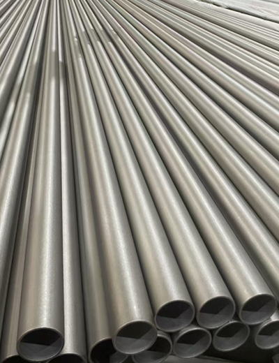
BS EN 10216-2:2024 Standard For Seamless Steel Tubes
BS EN 10216-2:2024 is the European standard for seamless steel tubes for pressure purposes, Part 2: Non-alloy and alloy steel tubes with specified elevated temperature properties. It is the part of the EN 10216 series specified when the service temperature climbs above ambient and the designer needs proof strength at temperature and creep rupture data rather than room-temperature values alone.
The 2024 edition was approved by CEN on 13 October 2024 and published by BSI on 30 November 2024. It supersedes BS EN 10216-2:2013+A1:2019, which is withdrawn. Preparation was entrusted in the UK to Technical Committee ISE/110, Steel Tubes, and Iron and Steel Fittings, and at the European level to CEN/TC 459 (ECISS) through sub-committee SC 10.
The standard covers 29 grade designations across three material families: non-alloy quality steels (P195GH, P235GH, P265GH), low-alloy molybdenum and chromium-molybdenum steels (16Mo3 through 11CrMo9-10), and 9 to 12 % chromium martensitic creep-resistant steels including X10CrMoVNb9-1, widely known as Grade 91. This guide covers the two test categories, the steel grades, heat treatment conditions, chemical composition, mechanical and creep properties, dimensional tolerances, inspection and testing requirements, the 19 options, marking, applications and FAQs.
BS EN 10216-2:2024 Free Download BS EN 10216-2:2024 Free Download
What is BS EN 10216-2:2024?
BS EN 10216-2:2024 specifies the technical delivery conditions, in two test categories, for seamless tubes of circular cross section with specified elevated temperature properties, made of non-alloy and alloy steel. The standard is also applicable to tubes of non-circular cross-section, with the necessary modifications agreed at the time of enquiry and order.
The document was prepared under standardization request M/601 addressed to CEN by the European Commission. Annex ZA sets out the relationship with Directive 2014/68/EU, the Pressure Equipment Directive. Once the standard is cited in the Official Journal of the European Union, compliance with the normative clauses listed in Table ZA.1 confers a presumption of conformity with the corresponding Essential Requirements, within the limits of the scope of the standard.
| Essential Requirement (2014/68/EU) | Clause of EN 10216-2:2024 | Subject |
| 4.1 a | 8.3 | Appropriate material properties |
| 4.1 c | 7.1 | Ageing |
| 4.1 d | 7.2 and 8.4 | Suitable for the processing procedures |
| 4.3 | 9 and 10 | Inspection documents |
Annex ZA carries two warnings that matter commercially. Presumption of conformity remains valid only while the reference to the standard is maintained in the Official Journal, so the list should be checked before relying on it. Other Union legislation may also apply to products within the scope of the standard.
The general technical delivery requirements of EN 10021:2006 apply in addition to this standard. Tubes shall be suitable for hot and cold bending, provided the bending is carried out in an appropriate manner. National standards bodies in 34 European countries are bound to implement the standard, and conflicting national standards were withdrawn in May 2025.
The EN 10216 Series: Five Parts Explained
EN 10216 is published in five parts under the general title "Seamless steel tubes for pressure purposes - Technical delivery conditions". Each part addresses a different service condition and material family, and Part 2 is the one written around elevated temperature behaviour.
| Standard | Scope | Material Family | Service Condition |
| EN 10216-1 | Non-alloy steel tubes with specified room temperature properties | Non-alloy steel | Room temperature |
| EN 10216-2 | Non-alloy and alloy steel tubes with specified elevated temperature properties | Non-alloy quality and alloy special steel | Elevated temperature |
| EN 10216-3 | Alloy fine-grain steel tubes | Alloy fine-grain steel | High strength |
| EN 10216-4 | Non-alloy and alloy steel tubes with specified low-temperature properties | Non-alloy and alloy steel | Low temperature |
| EN 10216-5 | Stainless steel tubes | Stainless steel | Corrosive service |
The parallel series for welded product is EN 10217, Welded steel tubes for pressure purposes - Technical delivery conditions. Where a weld seam is acceptable to the design code and the end user, EN 10217-2 is the welded counterpart to this part.
Under EN 10020:2000, the three GH grades P195GH, P235GH and P265GH are classified as non-alloy quality steels. Every other grade in the standard is classified as an alloy special steel. That classification is not academic: it determines which test category the tube can be ordered to.
Test Category 1 vs Test Category 2
The 2024 edition uses test categories, not the TR1/TR2 quality levels familiar from Part 1. The test category defines the extent and level of inspection and testing. It is mandatory order information for non-alloy steel, and it must be marked on the tube.
Non-alloy steel tubes are inspected and tested to test category 1 or test category 2 as specified at the time of enquiry and order. Alloy steel tubes are inspected and tested for category 2 only. There is no test category 1 option for an alloy grade.
| Parameter | Test Category 1 (TC1) | Test Category 2 (TC2) |
| Eligible grades | Non-alloy only: P195GH, P235GH, P265GH | All grades: mandatory for every alloy steel grade |
| Type of inspection | Specific inspection | Specific inspection |
| Sample tubes per test unit | One | Two (one where the test unit holds fewer than 20 tubes) |
| NDT for longitudinal imperfections | Not required | Mandatory on each tube |
| NDT for transverse imperfections (Option 8) | Not available | Available on each tube |
| NDT for laminar imperfections (Option 9) | Not available | Available on each tube |
| Cast analysis | One per cast | One per cast |
| Tensile test at room temperature | One per sample tube | One per sample tube |
| Leak tightness test | Each tube | Each tube |
| Marking | Test category shown for non-alloy grades | Test category shown for non-alloy grades |
The practical difference is the volume of non-destructive testing and the number of sample tubes drawn from each test unit. Test category 2 puts every tube through NDT for longitudinal imperfections and doubles the mechanical test sampling, which is why it is the only category permitted for the alloy creep-resistant grades.
BS EN 10216-2:2024 Steel Grades
Steel designation consists of the number of this part of EN 10216 plus either the steel name in accordance with EN 10027-1:2016 or the steel number allocated in accordance with EN 10027-2:2015.
For the non-alloy grades, the steel name is built from the capital letter P for pressure purposes, the specified minimum yield strength at room temperature for wall thickness up to and including 16 mm expressed in MPa, and the symbols GH for elevated temperature. P265GH therefore means a pressure-purpose steel with 265 MPa minimum yield in thin walls, characterised at elevated temperatures. Alloy grades are named from their chemical composition, with the heat treatment symbol appended where the standard specifies one, for example, X11CrMo9-1+NT.
Non-Alloy Quality Steels
Three grades, all supplied normalized, and the only grades in the standard that can be ordered to test category 1.
| Steel Name | Steel Number | Heat Treatment | Min Yield (T ≤ 16 mm) | Tensile Strength Rm | Elong. l / t |
| P195GH | 1.0348 | +N | 195 MPa | 320 to 440 MPa | 27 % / 25 % |
| P235GH | 1.0345 | +N | 235 MPa | 360 to 500 MPa | 25 % / 23 % |
| P265GH | 1.0425 | +N | 265 MPa | 410 to 570 MPa | 23 % / 21 % |
Low-Alloy Molybdenum and Chromium-Molybdenum Steels
This family carries most of the conventional elevated-temperature pipework in European plants. Molybdenum raises creep strength; chromium adds oxidation resistance and further creep capability as its content rises from 1 % in 13CrMo4-5 to 2.0 to 2.5 % in 10CrMo9-10.
| Steel Name | Steel Number | Heat Treatment | Min Yield (T ≤ 16 mm) | Tensile Strength Rm | Elong. l / t |
| 20MnNb6 | 1.0471 | +N | 355 MPa | 500 to 650 MPa | 22 % / 20 % |
| 16Mo3 | 1.5415 | +N | 280 MPa | 450 to 600 MPa | 22 % / 20 % |
| 8MoB5-4 | 1.5450 | +N | 400 MPa | 540 to 690 MPa | 19 % / 17 % |
| 14MoV6-3 | 1.7715 | +NT | 320 MPa | 460 to 610 MPa | 20 % / 18 % |
| 10CrMo5-5 | 1.7338 | +NT | 275 MPa | 410 to 560 MPa | 22 % / 20 % |
| 13CrMo4-5 | 1.7335 | +NT | 290 MPa | 440 to 590 MPa | 22 % / 20 % |
| 10CrMo9-10 | 1.7380 | +NT | 280 MPa | 480 to 630 MPa | 22 % / 20 % |
| 11CrMo9-10 | 1.7383 | +QT | 355 MPa | 540 to 680 MPa | 20 % / 18 % |
| 25CrMo4 | 1.7218 | +QT | 345 MPa | 540 to 690 MPa | 18 % / 15 % |
| 20CrMoV13-5-5 | 1.7779 | +QT | 590 MPa | 740 to 880 MPa | 16 % / 14 % |
| 15NiCuMoNb5-6-4 | 1.6368 | +NT | 440 MPa | 610 to 780 MPa | 19 % / 17 % |
| 7CrWVMoNb9-6 | 1.8201 | +NT | 400 MPa | 510 to 740 MPa | 20 % / 18 % |
| 7CrMoVTiB10-10 | 1.7378 | +NT | 450 MPa | 565 to 840 MPa | 17 % / 15 % |
5 % to 12 % Chromium Creep-Resistant Steels
The high-chromium grades cover the hottest duty in the standard. X11CrMo5 and X11CrMo9-1 are offered in isothermally annealed (+I) and normalized and tempered (+NT) conditions, and the yield strength difference between those conditions is substantial: 175 MPa for X11CrMo5+I against 390 MPa for X11CrMo5+NT2 in the same wall thickness.
| Steel Name | Steel Number | Heat Treatment | Min Yield (T ≤ 16 mm) | Tensile Strength Rm | Elong. l / t |
| X11CrMo5+I | 1.7362+I | +I | 175 MPa | 430 to 580 MPa | 22 % / 20 % |
| X11CrMo5+NT1 | 1.7362+NT1 | +NT1 | 280 MPa | 480 to 640 MPa | 20 % / 18 % |
| X11CrMo5+NT2 | 1.7362+NT2 | +NT2 | 390 MPa | 570 to 740 MPa | 18 % / 16 % |
| X11CrMo9-1+I | 1.7386+I | +I | 210 MPa | 460 to 640 MPa | 20 % / 18 % |
| X11CrMo9-1+NT | 1.7386+NT | +NT | 390 MPa | 590 to 740 MPa | 18 % / 16 % |
| X10CrMoVNb9-1 | 1.4903 | +NT | 450 MPa | 630 to 830 MPa | 19 % / 17 % |
| X10CrWMoVNb9-2 | 1.4901 | +NT | 440 MPa | 620 to 850 MPa | 19 % / 17 % |
| X11CrMoWVNb9-1-1 | 1.4905 | +NT | 450 MPa | 620 to 850 MPa | 19 % / 17 % |
| X20CrMoV11-1 | 1.4922 | +NT | 490 MPa | 690 to 840 MPa | 17 % / 14 % |
| X10CrSiCuMoNi9-2-1 | 1.7392 | +NT | 580 MPa | 750 to 950 MPa | 18 % / 18 % |
| X12CrCoWVNb12-2-2 | 1.4915 | +NT | 450 MPa | 620 to 850 MPa | 19 % / 17 % |
| X13CrCoWMoVNbBN11-2-2 | 1.4965 | +NT | 490 MPa | 650 to 880 MPa | 19 % / 17 % |
| X10CrMoVNb11 | 1.4927 | +NT | 450 MPa | 620 to 850 MPa | 19 % / 17 % |
X10CrMoVNb9-1 (1.4903) is the grade the power industry calls Grade 91, and X10CrWMoVNb9-2 (1.4901) is Grade 92. The 2024 edition specifically revised the creep rupture data for both grades using European Collaborative Creep Committee data sheets issued in 2019.
Manufacturing and Heat Treatment Conditions
All tubes are made by a seamless process. Unless Option 1 is specified, the tubes may be either hot or cold-finished; the terms refer to the condition of the tube before heat treatment. Option 1 requires the tubes to be cold-finished before heat treatment. Tubes are then supplied in the heat treatment condition specified in Table 1 of the standard for the grade concerned.
The steelmaking process is at the manufacturer's discretion, with one exclusion: the open hearth (Siemens-Martin) process is not permitted unless combined with a secondary steelmaking or ladle refining process. Steels shall be fully killed, which excludes rimming, balanced and semi-killed steel.
| Symbol | Heat Treatment | Representative Grades | Austenitizing Temperature |
| +N | Normalizing (includes normalizing forming, 880 °C to 1 000 °C) | P195GH, P235GH, P265GH, 20MnNb6, 16Mo3, 8MoB5-4 | 880 to 960 °C, air cooled |
| +NT | Normalizing and tempering | 14MoV6-3, 10CrMo5-5, 13CrMo4-5, 10CrMo9-10, X10CrMoVNb9-1 | 880 to 1 170 °C by grade, air-cooled |
| +QT | Quenching and tempering (air or liquid) | 11CrMo9-10, 25CrMo4, 20CrMoV13-5-5 | 860 to 1 030 °C |
| +I | Isothermal annealing, furnace atmosphere cooling | X11CrMo5+I, X11CrMo9-1+I | 890 to 980 °C |
Selected austenitizing and tempering ranges from Table 1, for the grades most often ordered:
| Steel Name | Heat Treatment | Austenitizing °C | Tempering °C |
| P235GH / P265GH | +N | 880 to 940 | - |
| 16Mo3 | +N | 890 to 950 | - |
| 13CrMo4-5 | +NT | 900 to 960 | 660 to 730 |
| 10CrMo9-10 | +NT | 900 to 960 | 680 to 750 |
| 11CrMo9-10 | +QT | 900 to 960 | 680 to 750 |
| X11CrMo9-1+NT | +NT | 890 to 950 | 720 to 800 |
| X10CrMoVNb9-1 | +NT | 1 040 to 1 090 | 730 to 780 |
| X10CrWMoVNb9-2 | +NT | 1 040 to 1 090 | 730 to 780 |
| X20CrMoV11-1 | +NT | 1 020 to 1 080 | 730 to 780 |
Two footnotes to Table 1 change the delivery condition in the heavy wall. For a number of the +NT grades, it may be necessary, where wall thickness exceeds 10 mm or the T/D ratio exceeds 0,15, to apply quenching and tempering instead in order to achieve the intended structure and properties. For 7CrWVMoNb9-6 and 7CrMoVTiB10-10, the same applies above 16 mm wall or T/D greater than 0,15. The decision has to be stated at the time of enquiry and order, and tubes treated that way are designated with the steel name supplemented by “+QT”.
All non-destructive testing activity has to be carried out by qualified and competent level 1, 2 or 3 personnel authorised in writing by the employer. Level 1 and 2 qualifications follow ISO 11484:2019 or EN ISO 9712:2022; level 3 qualification follows EN ISO 9712:2022. NDT operations are authorised by a level 3 individual approved by the employer.
Chemical Composition of BS EN 10216-2:2024
Chemical composition is specified as cast analysis in Table 2 of the standard, expressed in % by mass. The cast analysis reported by the steel producer applies. Elements not included in Table 2 shall not be intentionally added without the agreement of the purchaser, except for elements added to finish the cast, and measures must be taken to prevent undesirable elements from entering from scrap.
GH Grades and 20MnNb6
The three GH grades are the non-alloy quality steels of the standard. 20MnNb6 is classified as an alloy special steel, but sits close to them in composition and is shown alongside for comparison.
| Element | P195GH | P235GH | P265GH | 20MnNb6 |
| Carbon (C) | ≤ 0,13 | ≤ 0,16 | ≤ 0,20 | ≤ 0,22 |
| Silicon (Si) | ≤ 0,35 | ≤ 0,35 | ≤ 0,40 | 0,15 to 0,35 |
| Manganese (Mn) | ≤ 0,70 | ≤ 1,20 | ≤ 1,40 | 1,00 to 1,50 |
| Phosphorus (P) max | 0,025 | 0,025 | 0,025 | 0,025 |
| Sulfur (S) max | 0,010 | 0,010 | 0,010 | 0,010 |
| Chromium (Cr) | ≤ 0,30 | ≤ 0,30 | ≤ 0,30 | - |
| Molybdenum (Mo) | ≤ 0,08 | ≤ 0,08 | ≤ 0,08 | - |
| Nickel (Ni) | ≤ 0,30 | ≤ 0,30 | ≤ 0,30 | - |
| Aluminium (Al total) | ≥ 0,020 | ≥ 0,020 | ≥ 0,020 | ≤ 0,060 |
| Copper (Cu) | ≤ 0,30 | ≤ 0,30 | ≤ 0,30 | ≤ 0,30 |
| Niobium (Nb) | ≤ 0,010 | ≤ 0,020 | ≤ 0,020 | 0,015 to 0,10 |
| Titanium (Ti) max | 0,040 | 0,040 | 0,040 | - |
| Vanadium (V) | ≤ 0,02 | ≤ 0,02 | ≤ 0,02 | - |
| Cr + Cu + Mo + Ni | ≤ 0,70 | ≤ 0,70 | ≤ 0,70 | - |
Two conditions attach to the GH grades. The minimum total aluminium of 0,020 % is not applicable where the steel contains a sufficient amount of other nitrogen-binding elements, which then have to be reported; and the ratio Al/N shall be at least 2, except that where nitrogen is fixed by niobium, titanium or vanadium, the requirements for total aluminium and for Al/N do not apply. The contents of Nb, Ti and V need not be reported unless intentionally added to the cast. Sulfur is capped at 0,010 % across all three GH grades, a tighter limit than the room-temperature grades of Part 1 carry.
Low-Alloy Mo and CrMo Grades
| Steel Name | C | Si | Mn | Cr | Mo | Other |
| 16Mo3 | 0,12 to 0,20 | ≤ 0,35 | 0,40 to 0,90 | ≤ 0,30 | 0,25 to 0,35 | Al ≤ 0,040 |
| 8MoB5-4 | 0,06 to 0,10 | 0,10 to 0,35 | 0,60 to 0,80 | ≤ 0,20 | 0,40 to 0,50 | B 0,002 to 0,006; Ti ≤ 0,060 |
| 14MoV6-3 | 0,10 to 0,15 | 0,15 to 0,35 | 0,40 to 0,70 | 0,30 to 0,60 | 0,50 to 0,70 | V 0,22 to 0,28 |
| 10CrMo5-5 | ≤ 0,15 | 0,50 to 1,00 | 0,30 to 0,60 | 1,00 to 1,50 | 0,45 to 0,65 | Ni ≤ 0,30 |
| 13CrMo4-5 | 0,10 to 0,17 | ≤ 0,35 | 0,40 to 0,70 | 0,70 to 1,15 | 0,40 to 0,60 | Ni ≤ 0,30 |
| 10CrMo9-10 | 0,08 to 0,14 | ≤ 0,50 | 0,30 to 0,70 | 2,00 to 2,50 | 0,90 to 1,10 | P ≤ 0,020 |
| 11CrMo9-10 | 0,08 to 0,15 | ≤ 0,50 | 0,40 to 0,80 | 2,00 to 2,50 | 0,90 to 1,10 | Ni ≤ 0,30 |
| 25CrMo4 | 0,22 to 0,29 | ≤ 0,40 | 0,60 to 0,90 | 0,90 to 1,20 | 0,15 to 0,30 | Ni ≤ 0,3 |
| 20CrMoV13-5-5 | 0,17 to 0,23 | 0,15 to 0,35 | 0,30 to 0,50 | 3,00 to 3,30 | 0,50 to 0,60 | V 0,45 to 0,55 |
| 15NiCuMoNb5-6-4 | ≤ 0,17 | 0,25 to 0,50 | 0,80 to 1,20 | ≤ 0,30 | 0,25 to 0,50 | Ni 1,00 to 1,30; Cu 0,50 to 0,80; Nb 0,015 to 0,045 |
| 7CrWVMoNb9-6 | 0,04 to 0,10 | ≤ 0,50 | 0,10 to 0,60 | 1,90 to 2,60 | 0,05 to 0,30 | W 1,45 to 1,75; V 0,20 to 0,30; B 0,0010 to 0,006 |
| 7CrMoVTiB10-10 | 0,05 to 0,10 | 0,15 to 0,45 | 0,30 to 0,70 | 2,20 to 2,60 | 0,90 to 1,10 | V 0,20 to 0,30; Ti 0,05 to 0,10; B 0,0015 to 0,0070 |
For 16Mo3 and 13CrMo4-5, the upper carbon limit may be increased by 0,02 % for both cast and product analysis where wall thickness is 30 mm or greater.
5 % to 12 % Chromium Grades
| Steel Name | C | Cr | Mo | V | Nb | Other |
| X11CrMo5 (+I / +NT1 / +NT2) | 0,08 to 0,15 | 4,0 to 6,0 | 0,45 to 0,65 | - | - | Si 0,15 to 0,50 |
| X11CrMo9-1 (+I / +NT) | 0,08 to 0,15 | 8,0 to 10,0 | 0,90 to 1,10 | - | - | Si 0,25 to 1,00 |
| X10CrMoVNb9-1 | 0,08 to 0,12 | 8,0 to 9,5 | 0,85 to 1,05 | 0,18 to 0,25 | 0,06 to 0,10 | N 0,030 to 0,070; Ni ≤ 0,40 |
| X10CrWMoVNb9-2 | 0,07 to 0,13 | 8,5 to 9,5 | 0,30 to 0,60 | 0,15 to 0,25 | 0,04 to 0,09 | W 1,50 to 2,00; B 0,001 to 0,006 |
| X11CrMoWVNb9-1-1 | 0,09 to 0,13 | 8,5 to 9,5 | 0,90 to 1,10 | 0,18 to 0,25 | 0,06 to 0,10 | W 0,90 to 1,10; N 0,050 to 0,090 |
| X20CrMoV11-1 | 0,17 to 0,23 | 10,0 to 12,5 | 0,80 to 1,20 | 0,25 to 0,35 | - | Ni 0,30 to 0,80 |
| X10CrSiCuMoNi9-2-1 | 0,06 to 0,14 | 7,9 to 9,6 | 0,76 to 1,14 | - | - | Si 1,54 to 2,26; Cu 0,75 to 1,45; Ni 0,73 to 1,47 |
| X12CrCoWVNb12-2-2 | 0,08 to 0,16 | 10,85 to 12,15 | 0,16 to 0,44 | 0,17 to 0,33 | 0,025 to 0,085 | Co 1,30 to 1,80; W 1,20 to 1,80 |
| X13CrCoWMoVNbBN11-2-2 | 0,08 to 0,18 | 10,35 to 12,15 | 0,06 to 0,64 | 0,12 to 0,33 | 0,015 to 0,105 | Co 1,40 to 2,60; W 1,40 to 2,60; B 0,007 to 0,016 |
| X10CrMoVNb11 | 0,08 to 0,13 | 10,0 to 11,5 | 0,40 to 0,60 | 0,18 to 0,25 | 0,02 to 0,06 | N 0,030 to 0,070; Ni ≤ 0,20 |
For X20CrMoV11-1, the upper carbon value of 0,23 % shall not be exceeded on product analysis. For 7CrWVMoNb9-6, the standard sets a minimum Ti/N ratio of 3,5, and offers an alternative route: instead of the minimum ratio, the material may show a minimum hardness of 275 HV in the hardened condition, tested at mid-thickness on two samples per heat treatment lot, with the results reported.
Product Analysis Deviations
Option 3 calls for product analysis. Table 3 of the standard sets the permissible deviations from the cast analysis limits of Table 2, and the allowance widens as the specified level of the element rises.
| Element | Cast Analysis Limit (%) | Permissible Deviation (%) |
| C | ≤ 0,29 | ± 0,02 |
| Si | ≤ 0,40 / > 0,40 to ≤ 1,00 | ± 0,05 / ± 0,06 |
| Mn | ≤ 1,00 / > 1,00 to ≤ 1,50 | ± 0,05 / ± 0,10 |
| P | ≤ 0,030 | + 0,005 |
| S | ≤ 0,010 / > 0,010 to ≤ 0,020 | + 0,003 / + 0,005 |
| Al | ≤ 0,060 | ± 0,005 |
| B | ≤ 0,007 | + 0,0005 |
| Cr | ≤ 1,00 / > 1,00 to ≤ 10,0 / > 10,0 to ≤ 12,5 | ± 0,05 / ± 0,10 / ± 0,15 |
| Cu | ≤ 0,80 | ± 0,05 |
| Mo | ≤ 0,35 / > 0,35 to ≤ 1,20 | ± 0,03 / ± 0,04 |
| N | ≤ 0,070 | ± 0,01 |
| Nb | ≤ 0,10 | ± 0,005 |
| Ni | ≤ 0,35 / > 0,35 to ≤ 1,30 | ± 0,05 / ± 0,07 |
| Ti | ≤ 0,060 | + 0,010 |
| V | ≤ 0,10 / > 0,10 to ≤ 0,55 | + 0,01 / ± 0,03 |
| W | ≤ 2,00 | ± 0,10 |
Option 2 works in the other direction. Where subsequent forming operations need it, an agreed maximum copper content lower than the tabulated limit, together with an agreed maximum tin content, can be specified at enquiry and order.
Mechanical Properties of BS EN 10216-2:2024
Mechanical properties at and below room temperature are given in Table 4 and apply irrespective of whether they are verified on the order or not. Yield strength is banded by wall thickness, and the number of bands a grade carries depends on the thickness range the standard supports for it.
Yield Strength by Wall Thickness
| Steel Name | T ≤ 16 mm | 16 < T ≤ 40 mm | 40 < T ≤ 60 mm | 60 < T ≤ 100 mm |
| P195GH | 195 MPa | - | - | - |
| P235GH | 235 MPa | 225 MPa | 215 MPa | - |
| P265GH | 265 MPa | 255 MPa | 245 MPa | - |
| 20MnNb6 | 355 MPa | 345 MPa | 335 MPa | - |
| 16Mo3 | 280 MPa | 270 MPa | 260 MPa | - |
| 8MoB5-4 | 400 MPa | - | - | - |
| 14MoV6-3 | 320 MPa | 320 MPa | 310 MPa | - |
| 10CrMo5-5 | 275 MPa | 275 MPa | 265 MPa | - |
| 13CrMo4-5 | 290 MPa | 290 MPa | 280 MPa | - |
| 10CrMo9-10 | 280 MPa | 280 MPa | 270 MPa | - |
| 11CrMo9-10 | 355 MPa | 355 MPa | 355 MPa | - |
| 25CrMo4 | 345 MPa | 345 MPa | 345 MPa | - |
| 20CrMoV13-5-5 | 590 MPa | 590 MPa | 590 MPa | - |
| 15NiCuMoNb5-6-4 | 440 MPa | 440 MPa | 440 MPa | 440 MPa (60 < T ≤ 80 mm) |
| 7CrWVMoNb9-6 | 400 MPa | 400 MPa | 400 MPa | - |
| 7CrMoVTiB10-10 | 450 MPa | 430 MPa | 430 MPa | - |
| X11CrMo5+I | 175 MPa | 175 MPa | 175 MPa | 175 MPa |
| X11CrMo5+NT1 | 280 MPa | 280 MPa | 280 MPa | 280 MPa |
| X11CrMo5+NT2 | 390 MPa | 390 MPa | 390 MPa | 390 MPa |
| X11CrMo9-1+I | 210 MPa | 210 MPa | 210 MPa | - |
| X11CrMo9-1+NT | 390 MPa | 390 MPa | 390 MPa | - |
| X10CrMoVNb9-1 | 450 MPa | 450 MPa | 450 MPa | 450 MPa |
| X10CrWMoVNb9-2 | 440 MPa | 440 MPa | 440 MPa | 440 MPa |
| X11CrMoWVNb9-1-1 | 450 MPa | 450 MPa | 450 MPa | 450 MPa |
| X20CrMoV11-1 | 490 MPa | 490 MPa | 490 MPa | 490 MPa |
| X10CrSiCuMoNi9-2-1 | 580 MPa | 580 MPa | - | - |
| X12CrCoWVNb12-2-2 | 450 MPa | - | - | - |
| X13CrCoWMoVNbBN11-2-2 | 490 MPa | 490 MPa | 490 MPa | 490 MPa |
| X10CrMoVNb11 | 450 MPa | 450 MPa | 450 MPa | - |
Values are upper yield strength ReH, or the 0,2 % proof strength Rp0,2 where no yield phenomenon is present. Unlike the low-alloy grades, most of the 9 to 12 % chromium grades hold a single yield value across every thickness band the standard covers for them, which simplifies design in heavy wall header and main steam pipework.
Impact Properties
Minimum average absorbed energy KV2 is 40 J longitudinal and 27 J transverse, on the mean of three standard Charpy V-notch test pieces. What varies between grades is the test temperature and whether verification is mandatory or optional.
| Grade Group | Test Temperature | Longitudinal KV2 | Transverse KV2 | Verification |
| P195GH, P235GH, P265GH, 20MnNb6 | 0 °C | 40 J | 27 J | Option 4 or Option 5 |
| P195GH, P235GH, P265GH (Option 5) | − 10 °C | 28 J | - | Option 5, longitudinal only |
| All other grades | 20 °C | 40 J | 27 J | Option 4, or mandatory for T ≥ 16 mm on listed grades |
The standard divides the grades into two groups for impact testing. Group A covers tubes of wall thickness 16 mm and above made from 14MoV6-3, 25CrMo4, 20CrMoV13-5-5, 15NiCuMoNb5-6-4, X10CrSiCuMoNi9-2-1, X10CrMoVNb9-1, 7CrWVMoNb9-6, 7CrMoVTiB10-10, X10CrWMoVNb9-2, X11CrMoWVNb9-1-1, X20CrMoV11-1, X13CrCoWMoVNbBN11-2-2 and X10CrMoVNb11; the impact test at 20 °C is a mandatory test for Group A in both test categories. Group B covers those same grades below 16 mm wall plus all thicknesses of the remaining grades, and impact verification for Group B is an optional test invoked through Option 4.
Three practical rules govern specimen preparation. Impact tests are not required for specified wall thickness below 6 mm. Where standard 10 mm test pieces cannot be produced without flattening, narrower pieces down to 5 mm are used, and the measured energy is converted by KVc = 10 × KVp / w; where 5 mm cannot be obtained, the tubes are not impact tested at all. Test pieces are taken transverse to the tube axis unless Dmin, calculated as (T − 5) + [756,25 / (T − 5)], is greater than the specified outside diameter, in which case longitudinal pieces are used.
On the acceptance rule, the mean of three test pieces has to meet the specified value, and one individual value may fall below it, provided it is not less than 70 % of that value. If that fails, a second set of three may be tested; the unit then conforms only if the average of all six meets the minimum, no more than two of the six fall below the minimum, and no more than one of the six falls below 70 % of it.
Proof Strength at Elevated Temperature (Option 6)
This is the data that distinguishes Part 2 from Part 1. Minimum Rp0,2 values at temperature are tabulated in Table 5 of the standard, and Option 6 makes verification by tensile test at elevated temperature part of the order, with the test temperature specified at enquiry.
| Steel Name | Wall | 100 °C | 150 °C | 200 °C | 250 °C | 300 °C | 350 °C | 400 °C |
| P195GH | ≤16 mm | 175 | 165 | 150 | 130 | 113 | 102 | 94 |
| P235GH | ≤60 mm | 198 | 187 | 170 | 150 | 132 | 120 | 112 |
| P265GH | ≤60 mm | 226 | 213 | 192 | 171 | 154 | 141 | 134 |
| 20MnNb6 | ≤60 mm | 312 | 292 | 264 | 241 | 219 | 200 | 186 |
| 16Mo3 | ≤60 mm | 243 | 237 | 224 | 205 | 173 | 159 | 156 |
| 14MoV6-3 | ≤60 mm | 282 | 276 | 267 | 241 | 225 | 216 | 209 |
| 13CrMo4-5 | ≤60 mm | 264 | 253 | 245 | 236 | 192 | 182 | 174 |
| 10CrMo9-10 | ≤60 mm | 249 | 241 | 234 | 224 | 219 | 212 | 207 |
| 11CrMo9-10 | ≤60 mm | 323 | 312 | 304 | 296 | 289 | 280 | 275 |
| 20CrMoV13-5-5 | ≤60 mm | - | 575 | 570 | 560 | 550 | 510 | 470 |
| X11CrMo9-1+NT | ≤60 mm | 363 | 348 | 334 | 330 | 326 | 322 | 316 |
| X10CrMoVNb9-1 | ≤100 mm | 410 | 395 | 380 | 370 | 360 | 350 | 340 |
| X10CrWMoVNb9-2 | ≤100 mm | 420 | 412 | 405 | 400 | 392 | 382 | 372 |
| X20CrMoV11-1 | ≤100 mm | - | - | 430 | 415 | 390 | 380 | 360 |
| X10CrSiCuMoNi9-2-1 | ≤25 mm | 527 | 493 | 467 | 453 | 447 | 444 | 435 |
Values are a minimum of Rp0,2 in MPa. Table 5 in the standard runs from 100 °C to 400 °C in 50 °C steps; the columns above are a subset. For strength data above 400 °C, see the informative creep rupture strength values in Annex A (100 000 h basis), which is a different property (creep rupture strength, not proof strength).
Creep Rupture Strength (Annex A)
Annex A is informative and gives creep rupture strength values at 10 000 h, 100 000 h, 200 000 h and 250 000 h for each grade over the temperature range where that grade is characterised. The 100 000 h figure is the one most design codes work from.
| Steel Name | Characterised Range | 100 000 h at 450 °C | 100 000 h at 500 °C | 100 000 h at 550 °C | 100 000 h at 600 °C |
| P265GH | 400 to 500 °C | 77 MPa | 32 MPa | - | - |
| 16Mo3 | 450 to 550 °C | 236 MPa | 102 MPa | 32 MPa | - |
| 13CrMo4-5 / 10CrMo5-5 | 450 to 600 °C | 290 MPa | 145 MPa | 53 MPa | 20 MPa |
| 10CrMo9-10 | 450 to 600 °C | 229 MPa | 141 MPa | 70 MPa | 35 MPa |
| X20CrMoV11-1 | 480 to 650 °C | - | 236 MPa | 128 MPa | 59 MPa |
| X10CrMoVNb9-1 (Grade 91) | 500 to 670 °C | - | 241 MPa | 151 MPa | 84,2 MPa |
| X10CrWMoVNb9-2 (Grade 92) | 520 to 670 °C | - | - | 181 MPa | 112 MPa |
| X10CrSiCuMoNi9-2-1 | 410 to 700 °C | 257 MPa | 138 MPa | 69 MPa | 33 MPa |
The progression through that table is the whole argument for the standard's grade range. At 500 °C, P265GH holds 32 MPa for 100 000 h, while Grade 91 holds 241 MPa. At 600 °C, 10CrMo9-10 has fallen to 35 MPa where Grade 92 still holds 112 MPa. Grade selection under EN 10216-2 is a creep decision before it is a room-temperature strength decision.
Dimensions, Masses and Tolerances
Unless Option 11 is specified, tubes are delivered by outside diameter D and wall thickness T. Preferred dimensions are selected from EN 10220:2002 and listed in Table 6, covering outside diameters from 10,2 mm to 711 mm and wall thicknesses from 1,6 mm to 100 mm. Dimensions outside Table 6 may be agreed upon.
Table 6 sorts diameters into three series: series 1 covers diameters for which all the accessories needed to build a piping system are standardized, series 2 covers those for which not all accessories are standardized, and series 3 covers special-application diameters for which very few standardized accessories exist. Specifying a series 3 diameter usually means sourcing non-standard fittings alongside it.
Alternative Dimension Sets (Option 11)
Option 11 lets the purchaser order to a set of dimensions other than D and T, which matters where the bore has to be held rather than the outside surface:
| Dimension Set | Restriction |
| Outside diameter D and minimum wall thickness Tmin | No diameter restriction |
| Inside diameter d and wall thickness T | d ≥ 220 mm |
| Inside diameter d and minimum wall thickness Tmin | d ≥ 220 mm |
| Minimum inside diameter dmin and wall thickness T | dmin ≥ 220 mm |
| Minimum inside diameter dmin and minimum wall thickness Tmin | dmin ≥ 220 mm |
Where tubes are ordered by d, dmin or Tmin, calculated values Dc, dc and Tc are derived from the ordered dimension plus half the applicable tolerance and used in place of D, d and T for the requirements that depend on them, including the flattening test, the hydrostatic test pressure, dimensional inspection, NDT acceptance levels and marking.
Tolerances on Diameter and Wall Thickness
Out-of-roundness is included in the tolerance on diameter, and eccentricity is included in the tolerance on wall thickness. Which of the five tolerance tables applies depends on how the tube was ordered.
| Ordered By | Outside Diameter D | Tolerance on D | T/D ≤ 0,025 | > 0,025 to ≤ 0,050 | > 0,050 to ≤ 0,10 | > 0,10 |
| D and T (Table 7) | D ≤ 219,1 mm | ± 1 % or ± 0,5 mm, greater | ± 12,5 % or ± 0,4 mm, greater | ± 12,5 % or ± 0,4 mm, greater | ± 12,5 % or ± 0,4 mm, greater | ± 12,5 % or ± 0,4 mm, greater |
| D and T (Table 7) | D > 219,1 mm | ± 1 % or ± 0,5 mm, greater | ± 20 % | ± 15 % | ± 12,5 % | ± 10 % |
| Ordered By | Tolerance on Diameter | Tolerance on Thickness |
| Inside diameter d and T (Table 8) | ± 1 % or ± 2 mm, greater | ± 20 % (T/d ≤ 0,03), ± 15 % (> 0,03 to ≤ 0,06), ± 12,5 % (> 0,06 to ≤ 0,12), ± 10 % (> 0,12) |
| Minimum inside diameter dmin and T (Table 8) | + 2 % / 0 or + 4 mm / 0, greater | As above |
| D and Tmin (Table 9), D ≤ 219,1 mm | ± 1 % or ± 0,5 mm, greater | + 28 % / 0 or + 0,8 mm / 0, greater |
| D and Tmin (Table 9), D > 219,1 mm | ± 1 % or ± 0,5 mm, greater | + 50 % / 0 (Tmin/D ≤ 0,02), + 35 % / 0 (> 0,02 to ≤ 0,04), + 28 % / 0 (> 0,04 to ≤ 0,09), + 22 % / 0 (> 0,09) |
| d or dmin and Tmin (Table 10) | ± 1 % or ± 2 mm, greater; or + 2 % / 0 or + 4 mm / 0 for dmin | + 35 % / 0 (Tmin/d ≤ 0,05), + 28 % / 0 (> 0,05 to ≤ 0,1), + 22 % / 0 (> 0,1) |
| Cold finished (Table 11) | ± 0,5 % or ± 0,3 mm, greater | ± 10 % or ± 0,2 mm, greater |
Two points follow from those tables. Cold finished tube to Table 11 is roughly twice as tight on diameter as hot finished tube and holds ± 10 % on wall regardless of T/D ratio, which is why cold finished product is specified where fit-up tolerance is critical. And for outside diameters of 355,6 mm and above, Tables 7 to 10 permit the upper wall thickness to be exceeded locally by a further 5 % of T, with no restriction to a particular T/D band.
Mass
Mass per unit length follows EN 10220:2002, with grade-specific density corrections in place of the usual value:
| Density Used | Applicable Grades |
| 7,77 kg/dm³ | X11CrMo9-1+I, X11CrMo9-1+NT, X10CrMoVNb9-1, X20CrMoV11-1, X10CrMoVNb11 |
| 7,67 kg/dm³ | X10CrSiCuMoNi9-2-1 |
| 7,81 kg/dm³ | X12CrCoWVNb12-2-2, X13CrCoWMoVNbBN11-2-2 |
These are not rounding differences. On a large-bore header run, using the EN 10220 default instead of 7,67 kg/dm³ for X10CrSiCuMoNi9-2-1 overstates the theoretical mass by more than 2 %, which shows up directly in a weight-based purchase price.
Lengths, Straightness and End Preparation
Unless Option 12 is specified, tubes are delivered in random lengths, with the delivery length range agreed at the time of enquiry and order. Option 12 calls for exact lengths, and the tolerances are over-only:
| Length L | Tolerance on Exact Length |
| L ≤ 6 000 mm | + 10 mm / 0 |
| 6 000 < L ≤ 12 000 mm | + 15 mm / 0 |
| L > 12 000 mm | + by agreement / 0 |
Deviation from straightness shall not exceed 0,0015 L over any tube length L, and deviation over any one metre length shall not exceed 3 mm.
Tubes with a wall thickness of 3,2 mm and above are delivered with square-cut ends, free from excessive burrs. Option 10 calls for bevelled ends instead: a bevel angle of 30° (+5° / −0°) with a root face of 1,6 mm ± 0,8 mm, except that for wall thickness greater than 20 mm an agreed alternative bevel may be specified.
If you want to know more product details, please contact us!
Inspection and Testing Requirements
Conformity to the requirements of the order is verified by specific inspection for every tube supplied to this standard. Table 13 of the standard sets out which tests are mandatory, which are optional, how often each is carried out, and which test categories they apply to.
| Test / Inspection | Frequency | TC1 | TC2 |
| Cast analysis | One per cast | Mandatory | Mandatory |
| Tensile test at room temperature | One per sample tube | Mandatory | Mandatory |
| Flattening test or ring tensile test | One per sample tube | Mandatory | Mandatory |
| Drift expanding test or ring expanding test | One per sample tube | Mandatory | Mandatory |
| Impact test at 20 °C for Group A | One per sample tube | Mandatory | Mandatory |
| Leak tightness test | Each tube | Mandatory | Mandatory |
| Dimensional inspection | Per the manufacturer's procedure | Mandatory | Mandatory |
| Visual examination | Per the manufacturer's procedure | Mandatory | Mandatory |
| NDT for longitudinal imperfections | Each tube | Not applicable | Mandatory |
| Product analysis (Option 3) | One per cast | Optional | Optional |
| Tensile test at elevated temperature (Option 6) | One per cast and heat treatment condition | Optional | Optional |
| Impact test for Group B (Option 4) | One per sample tube | Optional | Optional |
| Longitudinal impact test at − 10 °C, non-alloy grades (Option 5) | One per sample tube | Optional | Optional |
| Wall thickness measurement away from tube ends (Option 15) | Per the agreed procedure | Optional | Optional |
| NDT for transverse imperfections (Option 8) | Each tube | Not applicable | Optional |
| NDT for laminar imperfections (Option 9) | Each tube | Not applicable | Optional |
| Material identification of alloy steels (Option 19) | Each tube | Optional | Optional |
The choice within each pair of forming tests is set by geometry. The flattening test applies where D is less than 600 mm, and the T/D ratio is 0,15 or less with T not exceeding 40 mm; the ring tensile test applies where D exceeds 150 mm, and T does not exceed 40 mm. The drift expanding test applies where D is 150 mm or less and T is 10 mm or less; the ring expanding test applies where D is 114,3 mm or less and T is 12,5 mm or less. For seven of the high-chromium grades - X10CrMoVNb9-1, X10CrWMoVNb9-2, X11CrMoWVNb9-1-1, X12CrCoWVNb12-2-2, X20CrMoV11-1, X13CrCoWMoVNbBN11-2-2 and X10CrMoVNb11 - these forming tests are carried out at one end of 20 % of the tubes of each test unit rather than on the sample tubes alone.
Test Units and Sampling
A test unit comprises tubes of the same specified diameter and wall thickness, the same steel grade, the same cast and the same manufacturing process. Where tubes are furnace heat treated, the unit is further restricted to tubes given the same finishing treatment in a continuous furnace, or heat treated in the same furnace charge in a batch-type furnace.
| Outside Diameter D | Maximum Tubes per Test Unit |
| D ≤ 114,3 mm | 200 |
| 114,3 < D ≤ 323,9 mm | 100 |
| D > 323,9 mm | 50 |
From each test unit, test category 1 draws one sample tube and test category 2 draws two, reduced to one where the test unit contains fewer than 20 tubes. Samples and test pieces are taken at the tube ends in accordance with EN ISO 377:2017.
Flattening, Drift Expanding and Ring Tests
The flattening test to EN ISO 8492:2013 presses the tube section until the distance H between platens reaches H = [(1 + C) / (C + T/D)] × T, where C is a constant factor of deformation given per grade in Table 15. C is 0,09 for P195GH and P235GH, 0,07 for P265GH, 20MnNb6, 16Mo3, 13CrMo4-5, 10CrMo9-10 and 11CrMo9-10, 0,08 for 10CrMo5-5, 0,06 for 25CrMo4, and 0,05 for the remaining alloy and high-chromium grades. After testing, the piece has to be free from cracks or breaks, though slight incipient cracks at the edges are not grounds for rejection, and cracks at the six and twelve o'clock positions are not cause for rejection where the D/T ratio is less than 10.
The drift expanding test to EN ISO 8493:2004 expands the tube with a 60° conical tool to a specified percentage increase in outside diameter that depends on the grade and on the d/D ratio, where d = D − 2T:
| Grade | d/D ≤ 0,6 | d/D > 0,6 to ≤ 0,8 | d/D > 0,8 |
| P195GH | 12 % | 15 % | 19 % |
| P235GH | 10 % | 12 % | 17 % |
| P265GH, 20MnNb6, 16Mo3 and most alloy grades | 8 % | 10 % | 15 % |
| 25CrMo4, 20CrMoV13-5-5, X20CrMoV11-1 | 6 % | 8 % | 12 % |
The ring tensile test to EN ISO 8496:2013 strains the tube section circumferentially to fracture, and the test pieces shall show no visible cracks without magnifying aids, excluding the fracture point. The ring expanding test to EN ISO 8495:2013 expands the section with a conical tool until it breaks, with the surface outside the fracture zone free from cracks or breaks.
Leak Tightness Testing
Tubes pass either a hydrostatic test or an electromagnetic test for leak tightness, unless Option 7 is specified, in which case the purchaser selects the method at enquiry and order.
The hydrostatic test is carried out at 7 MPa, or at a test pressure P calculated from P = 2 × (S × T) / D, whichever is lower, where S is the stress in MPa corresponding to 70 % of the specified minimum yield strength for the grade. The pressure is held for not less than 5 s for tubes with an outside diameter of 457 mm or less, and not less than 10 s above that. The tube shall withstand the test without showing leakage. The standard notes explicitly that this hydrostatic leak-tightness test is not a strength test. Option 14 allows a different test pressure to be specified.
The electromagnetic alternative is carried out in accordance with EN ISO 10893-1:2011.
Non-Destructive Testing
Tubes of test category 2 are subjected to NDT for the detection of longitudinal imperfections in accordance with EN ISO 10893-10:2011 to acceptance level U2, sub-category C, or EN ISO 10893-3:2011 to acceptance level F2, unless Option 16 fixes the method at enquiry and order. Regions at the tube ends not covered by the automated test are either tested manually or semi-automatically by ultrasonic testing to the same acceptance level or cropped off.
| Requirement | Reference Standard | Acceptance Level | Invoked By |
| Longitudinal imperfections | EN ISO 10893-10:2011 or EN ISO 10893-3:2011 | U2 sub-category C, or F2 | Mandatory for TC2 |
| Transverse imperfections | EN ISO 10893-10:2011 | U2 sub-category C | Option 8, TC2 only |
| Laminar imperfections | EN ISO 10893-8:2011 | U2 | Option 9, TC2 only |
| Hydraulic leak-tightness (electromagnetic) | EN ISO 10893-1:2011 | - | Alternative to hydrostatic test |
For tubes ordered by minimum wall thickness under Option 11, the acceptance level applies to the calculated wall thickness Tc rather than to the ordered Tmin.
Surface Condition and Dressing
Tubes shall be free from external and internal surface defects detectable by visual examination, with a finish typical of the manufacturing process and heat treatment used. Surface imperfections may be dressed by grinding or machining only, provided the wall thickness in the dressed area is not less than the specified minimum, and all dressed areas blend smoothly into the tube contour.
Any surface imperfection demonstrated to be deeper than 5 % of the wall thickness or 3 mm, whichever is smaller, has to be dressed; this does not apply to imperfections 0,3 mm deep or less. Imperfections that encroach on the specified minimum wall thickness are treated as defects, and tubes containing them do not conform to the standard.
Dimensional Inspection
Specified dimensions, including straightness, are verified. Outside diameter is measured at the tube ends, and for tubes of 406,4 mm outside diameter and above, a circumference tape may be used. Unless Option 15 is specified, wall thickness is measured at both tube ends; Option 15 moves the measurement away from the ends in accordance with an agreed procedure.
Inspection Documents and Certification
Inspection documents follow EN 10204:2004, and their content follows EN 10168:2004. Every inspection document has to carry a statement on the conformity of the products delivered with the requirements of the specification and the order.
| Document | How Obtained | Validated By | Notes |
| Inspection certificate 3.1 | Specified in the order (Clause 9.2.1) | Manufacturer's authorized representative | Manufacturer states in the order confirmation whether it operates a certified quality-assurance system assessed by a competent Body established within the Community |
| Inspection certificate 3.2 | Option 13 | Manufacturer's authorized representative | Purchaser notifies the manufacturer of the name and address of the organization or person carrying out the inspection; the parties agree on which of them issues the certificate |
The certificate content is specified by the EN 10168 code group, and knowing the codes makes reviewing a mill certificate considerably faster:
| Code | Content |
| A | Commercial transactions and parties involved |
| B | Description of products to which the inspection document applies |
| C02 - C03 | Direction of the test pieces and testing temperature |
| C10 - C13 | Tensile test |
| C40 - C43 | Impact test, if applicable |
| C60 - C69 | Other tests |
| C71 - C92 | Chemical composition of cast analysis and product analysis, if applicable |
| D01 | Marking and identification, surface appearance, shape and dimensional properties |
| D02 - D99 | Leak-tightness test, NDT and material identification, if applicable |
| Z | Validation |
The 19 Optional Requirements
Where none of the options are specified at the time of enquiry and order, the tubes are supplied to the basic specification: grade, dimensions, quantity, the term "tube" and, for non-alloy steel, the test category. The 19 options are how a purchaser moves the order beyond that baseline.
Two options deserve particular attention in an elevated-temperature order. Option 6 is the only route to a verified proof strength value at the design temperature; without it, the Table 5 values are specified properties that the order does not test. Option 18 matters because the standard default in Clause 13 is that tubes are delivered without any temporary protective coating, so protection for outdoor storage or sea freight has to be ordered explicitly.
Marking Requirements
Marking is applied indelibly on each tube, at least at one end. For tubes with an outside diameter of 51 mm or less, marking on the tube may be replaced by marking on a label attached to the bundle or box.
| Marking Element | Detail |
| Manufacturer's name or trade mark | Mandatory |
| Standard number and steel name | EN 10216-2 plus the steel name or number |
| Test category | For non-alloy steel grades |
| Cast number or code number | Mandatory |
| Mark of the inspection representative | Mandatory |
| Identification number | Order or item number permitting correlation to the related document |
A typical marking string reads X - EN 10216-2 - P265GH - TC1 - Y - Z1 - Z2, where X is the manufacturer's mark, TC1 is the test category, Y is the cast or code number, Z1 is the mark of the inspection representative, and Z2 is the identification number. Additional marking may be agreed under Option 17.
A typical order line for the same tube reads: 100 t - Tube - 168,3 x 4,5 - EN 10216-2 - P265GH - TC1 - Option 13: 3.2. For an alloy grade ordered by bore, the form is 100 m - Tube - dmin 240 x Tmin 40 - EN 10216-2 - 10CrMo9-10 - Option 13: 3.2, with no test category shown because alloy grades are supplied to test category 2 by default.
Applications of BS EN 10216-2:2024 Tubes
Boiler and Superheater Tubing
The grade ladder in this standard is built around boiler service. Below roughly 450 °C, P235GH and P265GH carry economiser and low-temperature evaporator duty. As metal temperature climbs, 16Mo3 takes over to around 550 °C, then 13CrMo4-5 and 10CrMo9-10 through to 600 °C, and finally the 9 to 12 % chromium martensitic grades for the hottest superheater and reheater elements. Annex A creep rupture data is the basis for that progression, not a rule of thumb.
Main Steam and Header Pipework
X10CrMoVNb9-1 and X10CrWMoVNb9-2, better known as Grade 91 and Grade 92, hold characterised creep data to 670 °C and single yield strength values across wall thicknesses up to 100 mm. That combination is what makes them the working grades for main steam lines and thick-wall headers in a supercritical plant, where a thinner wall at the same design pressure reduces both weight and thermal fatigue duty.
Process Heaters and Refinery Service
X11CrMo5 and X11CrMo9-1, in both isothermally annealed and normalized and tempered conditions, cover fired heater coils and elevated-temperature process lines where chromium content is specified for oxidation and sulfidation resistance as much as for creep strength. The +I and +NT conditions of the same composition give very different strength levels, so the delivery condition has to be part of the specification, not an assumption.
Pressure Vessel and Heat Exchanger Tubing
16Mo3 and 13CrMo4-5 are the routine choices for heat exchanger and pressure vessel tubing operating above the range Part 1 covers. Where the process stream is corrosive rather than simply hot, the correct specification moves to EN 10216-5 for stainless steel tubes, since none of the grades in Part 2 are selected for corrosion resistance.
What Changed in the 2024 Edition
Annex B lists the significant technical changes made to EN 10216-2:2013+A1:2019. Anyone holding stock or drawings against the previous edition should read the list rather than assume continuity.
| Area | Change |
| Normative references | Updated throughout |
| Options | Option 19, material positive identification, modified in 6.2 |
| NDT personnel | Text in 7.2.1 modified, covering level 1, 2 and 3 qualifications and written authorization |
| Steel grades | New steel grades added |
| Preferred dimensions | Correction inserted in Table 6 |
| Inspection | Text in 9.1 and 9.2.1 modified |
| Impact test pieces | New sentence inserted in 10.2.2.4 |
| Hydrostatic test | Unit in 11.8.1 changed from bar to MPa |
| Material identification | Text in 11.12 modified |
| Creep rupture data | Table A.1 updated by corrections and amendments; ECCC 2019 data sheets for X10CrMoVNb9-1 (Grade 91) and X10CrWMoVNb9-2 (Grade 92) adopted |
The bar-to-MPa change in 11.8.1 is the one most likely to cause a procedural error: the hydrostatic test pressure is now stated as 7 MPa where the previous edition expressed it as 70 bar. The value is the same, but test procedures and inspection records that quote the clause should be updated to match the current wording.
Frequently Asked Questions
-
What Is the Difference Between EN 10216-1 and EN 10216-2?
-
What Is the Difference Between Test Category 1 and Test Category 2?Every alloy steel grade in the standard requires test category 2. For non-alloy grades P195GH, P235GH, and P265GH, buyers can choose test category 1 instead. Test category 2 doubles the destructive sampling rate to two tubes per test unit and mandates non-destructive testing for longitudinal imperfections across every single length. Choosing category 2 also unlocks optional non-destructive testing for transverse defects under Option 8 and laminar defects under Option 9.
-
Does BS EN 10216-2:2024 Support CE Marking Under the PED?Annex ZA sets out the relationship between the standard and Directive 2014/68/EU. Once the standard is cited in the Official Journal of the European Union, compliance with the clauses in Table ZA.1 confers a presumption of conformity with the corresponding Essential Requirements, within the scope of the standard. The annex warns that the presumption stays valid only while the citation is maintained, and that other Union legislation may also apply.
-
What Is Grade 91 in EN 10216-2 Terms?Grade 91 is X10CrMoVNb9-1, steel number 1.4903, supplied normalized and tempered with austenitizing at 1 040 to 1 090 °C and tempering at 730 to 780 °C. It has 450 MPa minimum yield across wall thicknesses up to 100 mm, a tensile strength of 630 to 830 MPa, and creep rupture data in Annex A from 500 °C to 670 °C. Grade 92 is X10CrWMoVNb9-2, steel number 1.4901. The 2024 edition revised the creep data for both grades from the ECCC 2019 data sheets.
-
What Hydrostatic Test Pressure Applies?The lower of 7 MPa or the pressure calculated from P = 2 × (S × T) / D, where S is the stress corresponding to 70 % of the specified minimum yield strength for the grade. Hold time is at least 5 s for outside diameters up to and including 457 mm and at least 10 s above that. The standard states that this is a leak-tightness test and not a strength test. Option 14 permits a different test pressure by agreement.
-
When Is Impact Testing Mandatory?Impact testing at 20 °C is a mandatory test for Group A: tubes of wall thickness 16 mm and above in the thirteen listed alloys and high-chromium grades. For Group B, which covers those grades below 16 mm wall plus all thicknesses of the remaining grades, impact verification is optional under Option 4. Impact tests are not required at all for specified wall thickness below 6 mm or where test pieces at least 5 mm wide cannot be obtained from the wall.
-
Are Elevated Temperature Properties Tested on Every Order?No. The Table 5 proof strength values at elevated temperature apply as specified properties, but verification by tensile test at temperature happens only when Option 6 is specified, and the test temperature has to be nominated at enquiry and order. The test is carried out to EN ISO 6892-2:2018, one per cast and heat treatment condition. The creep rupture values in Annex A are informative and are not verified by tests under this standard.
-
What Dimensional Range Does the Standard Cover?Preferred dimensions from EN 10220:2002 cover outside diameters from 10,2 mm to 711 mm and wall thicknesses from 1,6 mm to 100 mm, sorted into three series by the availability of standardized piping accessories. Dimensions outside Table 6 may be agreed between the manufacturer and buyer, and Option 11 allows ordering by inside diameter or minimum wall thickness within the stated restrictions.
-
Are the Tubes Supplied with Corrosion Protection?No. Clause 13 states that tubes are delivered without a temporary protective coating. Option 18 has to be specified to obtain a temporary protective coating, or a durable coating and/or lining. This matters for the low-alloy grades in particular, since they offer no inherent corrosion resistance during storage or transit.
-
Under what conditions can specific steelmaking processes be used, and what deoxidation state is required?The manufacturer determines the steelmaking process, except for the open hearth (Siemens-Martin) process, which can only be used if combined with a secondary steelmaking or ladle refining process. Steels are required to be fully killed, explicitly excluding rimmed, balanced, and semi-killed steels.
-
Does EN 10216-2 Cover Welded Tubes?No, EN 10216-2 covers seamless steel tubes exclusively, excluding all welded alternatives. Engineers requiring welded pressure tubing must specify the EN 10217 series instead.