
TR2 supports the Essential Requirements of the Pressure Equipment Directive 97/23/EC; TR1 does not. TR2 requires mandatory Charpy impact testing at 0°C, tighter sulfur (0.015% vs 0.020%), a minimum aluminium content of 0.020%, and an EN 10204 inspection certificate 3.1. TR1 requires only a test report 2.2 and permits non-specific inspection. If the tube goes into CE-marked pressure equipment, TR2 is mandatory.

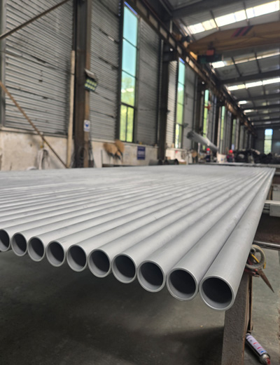
BS EN 10216-1:2013 Standard For Seamless Steel Tubes
BS EN 10216-1:2013 is the European standard for seamless steel tubes for pressure purposes, Part 1: Non-alloy steel tubes with specified room temperature properties. It is the entry point of the EN 10216 series: the specification you reach for when the pressure system runs at ambient temperature and non-alloy quality steel does the job.
The standard defines two quality levels (TR1 and TR2) across three steel grades: P195, P235, and P265. TR2 carries mandatory impact testing and supports the Pressure Equipment Directive (PED) 97/23/EC; TR1 does not. That single distinction drives most specification decisions under this standard.
BS EN 10216-1 seamless tubes are specified for compressed air lines, water and steam distribution, hydraulic circuits, boiler feed piping, and general industrial pressure systems across the UK and EU. This page covers the quality levels, steel grades, chemical composition, mechanical properties, dimensional tolerances, delivery conditions, inspection documents, testing requirements, the 13 optional requirements, and FAQs.
BS EN 10216-1:2013 Free Download BS EN 10216-1:2013 Free Download
What is BS EN 10216-1:2013?
BS EN 10216-1:2013 specifies the technical delivery conditions for two qualities (TR1 and TR2) of seamless tubes of circular cross section with specified room temperature properties, made of non-alloy quality steel. It was prepared by Technical Committee ECISS/TC 110 (Steel tubes and fittings for steel tubes) and supersedes EN 10216-1:2002.
The standard was published under the EU Pressure Equipment Directive 97/23/EC. Presumption of conformity to the Essential Safety Requirements applies to the material data in the standard, but not to the adequacy of the material for a specific item of equipment. The designer or manufacturer of the pressure equipment must verify that the ESRs are satisfied, accounting for subsequent manufacturing processes that may affect base material properties.
National standards organisations across 33 European countries implement this standard, including the UK, Germany, France, Italy, Spain, Netherlands, and Turkey.
The EN 10216 Series: Five Parts Explained
EN 10216-1 is one part of a five-part series covering seamless steel tubes for pressure purposes. Each part targets a different service condition and material family. Selecting the wrong part is the most common specification error engineers make with this series.
| Standard | Scope | Material Family | Service Condition |
| EN 10216-1 | Non-alloy steel tubes, room temperature properties | Non-alloy (carbon) steel | Ambient temperature |
| EN 10216-2 | Non-alloy and alloy steel tubes, elevated temperature properties | Non-alloy and alloy steel | Elevated temperature |
| EN 10216-3 | Alloy fine grain steel tubes | Alloy fine grain steel | High strength applications |
| EN 10216-4 | Non-alloy and alloy steel tubes, low temperature properties | Non-alloy and alloy steel | Cryogenic / low temperature |
| EN 10216-5 | Stainless steel tubes | Austenitic, duplex, ferritic SS | Corrosive / high-temp service |
For corrosion-resistant pressure tubing, stainless steel seamless tube is specified to EN 10216-5, which covers austenitic, austenitic-ferritic (duplex), and ferritic stainless grades. EN 10216-1 covers only non-alloy carbon steel and offers no corrosion resistance beyond what a protective coating provides.
The welded-tube counterpart to this series is EN 10217 (Welded steel tubes for pressure purposes). When welded manufacturing is acceptable and the cost saving matters, EN 10217-1 is the direct equivalent of EN 10216-1.
TR1 vs TR2: The Two Quality Levels
The TR1/TR2 distinction is the single most important decision in EN 10216-1. It determines whether the tube supports PED compliance, whether impact testing is mandatory, and which inspection document you receive.
| Parameter | Quality TR1 | Quality TR2 |
| PED 97/23/EC Support | No — does not support ESRs | Yes — supports ESRs |
| Impact Testing | Not required | Mandatory at 0 °C |
| Inspection Document | Test report 2.2 | Inspection certificate 3.1 |
| Inspection Type | Non-specific or specific | Specific inspection only |
| Sulfur, max (%) | 0.020 | 0.015 |
| Aluminium (Al total) | Not specified | 0.020 min |
| Delivery Condition (hot formed) | As formed, normalised, or normalising-formed | Normalised or normalising-formed |
| Cast Separation (D ≤ 76.1 mm) | Not applicable | Not required unless Option 10 |
| Test Unit Size (D ≤ 114.3 mm) | 400 tubes max | 200 tubes max |
| Steel Numbers | 1.0107, 1.0254, 1.0258 | 1.0108, 1.0255, 1.0259 |
The practical rule: if the tube goes into pressure equipment that must carry a CE mark under the Pressure Equipment Directive, specify TR2. TR1 grades explicitly do not support the Essential Requirements of the New Approach Directive 97/23/EC. TR1 is appropriate for non-PED applications, structural pressure use, and markets outside EU regulatory scope.
BS EN 10216-1 Steel Grades
The standard covers three steel grades, each available in both TR1 and TR2 quality. The designation follows EN 10027-1: the letter P indicates pressure purposes, the number indicates minimum yield strength in MPa for the thinnest wall section, and the TR suffix indicates the quality level.
| Steel Name | Steel Number | Min Yield (T ≤ 16 mm) | Tensile Range | Carbon, max |
| P195TR1 | 1.0107 | 195 MPa (28 ksi) | 320–440 MPa (46–64 ksi) | 0.13% |
| P195TR2 | 1.0108 | 195 MPa (28 ksi) | 320–440 MPa (46–64 ksi) | 0.13% |
| P235TR1 | 1.0254 | 235 MPa (34 ksi) | 360–500 MPa (52–73 ksi) | 0.16% |
| P235TR2 | 1.0255 | 235 MPa (34 ksi) | 360–500 MPa (52–73 ksi) | 0.16% |
| P265TR1 | 1.0258 | 265 MPa (38 ksi) | 410–570 MPa (59–83 ksi) | 0.20% |
| P265TR2 | 1.0259 | 265 MPa (38 ksi) | 410–570 MPa (59–83 ksi) | 0.20% |
P195 (1.0107 / 1.0108)
P195 is the lowest-strength grade with 195 MPa (28 ksi) minimum yield and 0.13% maximum carbon. Low carbon gives excellent formability and weldability. P195 is specified for compressed air lines, low-pressure water systems, and applications where the tube will be extensively cold-bent or formed after delivery. It also offers the highest elongation at 27% longitudinal.
P235 (1.0254 / 1.0255)
P235 is the workhorse grade of EN 10216-1, with 235 MPa (34 ksi) minimum yield and 0.16% maximum carbon. It balances strength, weldability, and cost, which is the same reason ASTM A106 Grade B dominates the North American carbon steel pipe market. P235TR2 is the most widely ordered designation in the standard for general industrial pressure piping across Europe.
P265 (1.0258 / 1.0259)
P265 is the highest-strength grade at 265 MPa (38 ksi) minimum yield and 0.20% maximum carbon. The higher carbon and manganese (1.40% max vs 1.20% for P235) deliver more strength but reduce elongation to 21% longitudinal. P265 is specified when wall thickness reduction matters for weight or cost, and where the tube will not undergo severe cold forming.
Chemical Composition of BS EN 10216-1
Chemical composition is defined as cast analysis in Table 2 (TR2) and Table 3 (TR1) of the standard, expressed in % by mass. Two elements differ between the quality levels: sulfur is tighter in TR2 (0.015% vs 0.020%), and TR2 requires a minimum aluminium content of 0.020% for grain refinement.
| Element | P195 (max) | P235 (max) | P265 (max) | Notes |
| Carbon (C) | 0.13 | 0.16 | 0.20 | Drives strength and weldability |
| Silicon (Si) | 0.35 | 0.35 | 0.40 | Deoxidiser |
| Manganese (Mn) | 0.70 | 1.20 | 1.40 | Strength and hardenability |
| Phosphorus (P) | 0.025 | 0.025 | 0.025 | Same for TR1 and TR2 |
| Sulfur (S) — TR1 | 0.020 | 0.020 | 0.020 | Looser limit |
| Sulfur (S) — TR2 | 0.015 | 0.015 | 0.015 | Tighter for impact toughness |
| Aluminium (Al total) — TR2 | 0.020 min | 0.020 min | 0.020 min | Grain refining, min not max |
| Chromium (Cr) | 0.30 | 0.30 | 0.30 | Residual limit |
| Molybdenum (Mo) | 0.08 | 0.08 | 0.08 | Residual limit |
| Nickel (Ni) | 0.30 | 0.30 | 0.30 | Residual limit |
| Copper (Cu) | 0.30 | 0.30 | 0.30 | Residual limit |
| Niobium (Nb) | 0.010 | 0.010 | 0.010 | Micro-alloying limit |
| Titanium (Ti) | 0.04 | 0.04 | 0.04 | Micro-alloying limit |
| Vanadium (V) | 0.02 | 0.02 | 0.02 | Micro-alloying limit |
| Cr + Cu + Mo + Ni | 0.70 | 0.70 | 0.70 | Combined residual cap |
Note on aluminium: the 0.020 % minimum total aluminium for TR2 is not applicable where the steel contains a sufficient amount of other nitrogen binding elements, which must then be reported. Aluminium is specified as a minimum for grain refinement and nitrogen fixing, not as a maximum residual limit.
Note: Steels must be fully killed, and this excludes rimming, balanced, and semi-killed steel. The open hearth (Siemens-Martin) process is not permitted unless combined with secondary steelmaking or ladle refining. The 0.70% combined cap on Cr + Cu + Mo + Ni prevents residual element accumulation from scrap-based steelmaking that would compromise weldability.
Product analysis tolerances (Option 3) permit the following deviations from the cast analysis limits of Tables 2 and 3.
| Element | Cast Analysis Limit (%) | Permissible Deviation (%) |
| C | 0.20 | ± 0.02 |
| Si | 0.40 | ± 0.05 |
| Mn | 1.40 | ± 0.10 |
| P | 0.025 | + 0.005 |
| S | 0.020 (TR1) | + 0.005 |
| S | 0.015 (TR2) | + 0.003 |
| Al | 0.020 | − 0.005 |
| Cr | 0.30 | ± 0.05 |
| Cu | 0.30 | ± 0.05 |
| Mo | 0.08 | ± 0.02 |
| Nb | 0.010 | ± 0.005 |
| Ni | 0.30 | ± 0.05 |
| Ti | 0.04 | + 0.01 |
| V | 0.02 | + 0.01 |
Mechanical Properties of BS EN 10216-1
Mechanical properties are defined in Table 5 (TR2) and Table 6 (TR1). Tensile and elongation requirements are identical for both quality levels. The difference is that TR2 adds mandatory impact energy requirements. Yield strength decreases as wall thickness increases, reflecting the reduced cooling rate and coarser grain structure in thicker sections.
Tensile Properties (TR1 and TR2)
Upper yield strength varies by wall thickness; tensile strength and elongation are constant across the thickness range.
| Steel Grade | Yield (T ≤ 16 mm) | Yield (16 < T ≤ 40) | Yield (40 < T ≤ 60) | Tensile Rm | Elong. Long. / Trans. |
| P195 | 195 MPa (28 ksi) | 185 MPa (27 ksi) | 175 MPa (25 ksi) | 320–440 MPa (46–64 ksi) | 27% / 25% |
| P235 | 235 MPa (34 ksi) | 225 MPa (33 ksi) | 215 MPa (31 ksi) | 360–500 MPa (52–73 ksi) | 25% / 23% |
| P265 | 265 MPa (38 ksi) | 255 MPa (37 ksi) | 245 MPa (36 ksi) | 410–570 MPa (59–83 ksi) | 21% / 19% |
Impact Properties (TR2 Only)
Charpy V-notch impact testing is mandatory for TR2 at 0 °C (32 °F). The minimum average absorbed energy from three test pieces is listed below. TR1 grades carry no impact requirement.
| Steel Grade | Longitudinal at 0 °C | Longitudinal at −10 °C (Option 4) | Transverse at 0 °C |
| P195TR2 | 40 J | 28 J | 27 J |
| P235TR2 | 40 J | 28 J | 27 J |
| P265TR2 | 40 J | 28 J | 27 J |
Note: The mean of three test pieces must meet the specified value. One individual value may fall below, provided it is not less than 70% of that value. For wall thickness greater than 60 mm, mechanical properties are subject to agreement between purchaser and manufacturer.
Delivery Conditions and Manufacturing
All tubes are manufactured by a seamless process. The delivery condition depends on the forming operation and the quality level.
| Forming Operation | Quality | Delivery Condition |
| Hot formed | TR1 | As formed, normalised, or normalising-formed |
| Hot formed | TR2 | Normalised or normalising-formed |
| Hot formed + cold finished | TR1 and TR2 | Normalized |
Option 1 allows the purchaser to require normalised or normalising-formed delivery condition for hot-formed TR1 tubes, removing the manufacturer’s discretion to supply in the as-formed condition. Cold-finished tubes are always normalised regardless of quality level, because cold working introduces residual stress and directional properties that normalising removes.
Dimensions and Tolerances
Tubes are delivered by outside diameter (D) and wall thickness (T). Preferred dimensions are selected from EN 10220 and listed in Table 7 of the standard, covering outside diameters from 10.2 mm to 711 mm and wall thicknesses from 1.6 mm to 100 mm. Dimensions outside Table 7 may be agreed.
Diameter and Wall Thickness Tolerances (Table 8)
Out-of-roundness is included in the outside diameter tolerance; eccentricity is included in the wall thickness tolerance. Wall tolerance depends on the T/D ratio.
| Outside Diameter D | Tolerance on D | T/D ≤ 0.025 | 0.025 < T/D ≤ 0.050 | 0.050 < T/D ≤ 0.10 | T/D > 0.10 |
| D ≤ 219.1 mm | ±1% or ±0.5 mm (greater) | ±12.5% or ±0.4 mm (greater) | ±12.5% or ±0.4 mm | ±12.5% or ±0.4 mm | ±12.5% or ±0.4 mm |
| D > 219.1 mm | ±1% or ±0.5 mm (greater) | ±20% | ±15% | ±12.5% | ±10% |
Note: For outside diameters D ≥ 355.6 mm, the upper wall thickness may be locally exceeded by a further 5% of the wall thickness T. This local allowance accommodates the mandrel and roll wear patterns inherent in large-diameter seamless tube production.
Length Tolerances (Table 9)
Unless Option 8 is specified, tubes are delivered in random lengths with the range agreed at enquiry. For exact lengths (Option 8), the tolerances are strictly over-only:
| Length L | Tolerance on Exact Length |
| L ≤ 6,000 mm | +10 mm / 0 |
| 6,000 < L ≤ 12,000 mm | +15 mm / 0 |
| L > 12,000 mm | +by agreement / 0 |
Straightness and End Preparation
Deviation from straightness shall not exceed 0.0015 L for any tube length L, and deviation over any one metre shall not exceed 3 mm. Tubes with wall thickness up to and including 3.2 mm are delivered with square cut ends, free from excessive burrs. Option 7 covers tubes with wall thickness above 3.2 mm, which are delivered with bevelled ends at a 30° (+5°/−0°) angle and a 1.6 ± 0.8 mm root face. For wall thickness greater than 20 mm, an alternative bevel may be agreed between purchaser and manufacturer.
If you want to know more product details, please contact us!
Inspection and Testing Requirements
Testing requirements differ sharply between TR1 and TR2. TR2 adds mandatory impact testing and requires a higher-grade inspection document.
| Test / Inspection | TR1 Frequency | TR2 Frequency |
| Cast analysis | One per cast (specific) or one per delivery item | One per cast |
| Tensile test | One per test unit | One per test unit |
| Impact test at 0 °C | Not required | One per test unit (mandatory) |
| Leak-tightness test | Each tube | Each tube |
| Dimensional inspection | Per Clause 11.5 | Per Clause 11.5 |
| Visual examination | Per Clause 11.6 | Per Clause 11.6 |
| Product analysis (Option 3) | Not applicable | One per cast (optional) |
| Impact at −10 °C (Option 4) | Not applicable | One per test unit (optional) |
| NDT for longitudinal defects (Option 6) | Not applicable | Each tube (optional) |
Hydrostatic Leak-Tightness Test
The hydrostatic test is carried out at 70 bar (7 MPa / 1,015 psi) or at pressure P calculated by P = 20 × (S × T) / D, whichever is lower. Here S is the stress in MPa corresponding to 70% of the specified minimum yield strength. Pressure is held for not less than 5 seconds for D ≤ 457 mm, and not less than 10 seconds for D > 457 mm. The standard explicitly notes this is a leak-tightness test, not a strength test.
Electromagnetic Test Alternative
In place of the hydrostatic test, an electromagnetic test per EN ISO 10893-1 may be used. Unless Option 5 is specified, the choice of test method is at the manufacturer’s discretion.
Non-Destructive Testing (Option 6)
When Option 6 is specified, TR2 tubes undergo NDT for detection of longitudinal imperfections per EN ISO 10893-2 (eddy current), EN ISO 10893-3 (flux leakage), or EN ISO 10893-10 (ultrasonic) to acceptance level 3, sub-category C. The purchaser specifies which method applies. Tube end regions not covered by automated testing must either be tested manually or semi-automatically by ultrasonic testing per EN ISO 10893-10, or cropped off.
Test Unit Size (Table 12)
The maximum number of tubes per test unit depends on outside diameter and quality level. TR2 test units are half the size of TR1 units, reflecting the higher assurance level.
| Outside Diameter D | Quality TR1 | Quality TR2 |
| D ≤ 114.3 mm | 400 tubes | 200 tubes |
| 114.3 < D ≤ 323.9 mm | 200 tubes | 100 tubes |
| D > 323.9 mm | 100 tubes | 50 tubes |
Inspection Documents and Certification
Inspection documents follow EN 10204. TR1 receives a test report 2.2; TR2 receives an inspection certificate 3.1. Option 9 allows the purchaser to upgrade either quality level to a 3.2 certificate. Where a 3.2 is specified, the purchaser notifies the manufacturer of the name and address of the organisation or person who will carry out the inspection and produce the document, and the parties agree which of them issues the certificate. Documents 3.1 and 3.2 are both validated by the manufacturer's authorised representative.
| Quality / Option | Document Type | Validated By | Description |
| TR1 (default) | Test report 2.2 | Manufacturer | Non-specific inspection permitted |
| TR2 (default) | Inspection certificate 3.1 | Manufacturer’s authorised representative | Specific inspection required |
| TR1 (Option 9) | Inspection certificate 3.2 | Manufacturer's authorised representative | Specific inspection required, purchaser nominates the inspecting party |
| TR2 (Option 9) | Inspection certificate 3.2 | Manufacturer's authorised representative | Highest assurance level, purchaser nominates the inspecting party |
When a 3.1 certificate is specified, the material manufacturer must state in the order confirmation whether it operates a certified quality-assurance system assessed by a competent Body established within the Community. This declaration is a PED compliance requirement, not merely a commercial formality. Our certificates and approvals page lists the third-party approvals held.
The 13 Optional Requirements
EN 10216-1 defines 13 numbered options the purchaser can invoke at enquiry and order. Understanding these options is the difference between a tube that meets your actual requirements and one that merely meets the default standard.
For tubes with outside diameter of 76.1 mm or less, Option 3 applies only when Option 11 is specified alongside it, because the analysis sample has to come from a location away from the tube ends.
Option 13 deserves particular attention: the standard default is that tubes are delivered with no protective coating. Non-alloy carbon steel tubes will begin surface rusting within days of exposure to humid air. If the tubes will be stored outdoors or shipped by sea, invoke Option 13 or arrange coating separately.
Marking Requirements
Marking is applied indelibly on each tube at least at one end. For tubes with outside diameter D ≤ 51 mm, marking may be replaced by a label attached to the bundle or box.
Mandatory marking includes the manufacturer’s name or trade mark and the standard number plus steel name. For specific inspection, marking additionally includes the cast number or code number, the mark of the inspection representative, and an identification number permitting correlation of the product to related documents. A typical marking reads: X – EN 10216-1 – P265TR2 – Y – Z₁ – Z₂.
Key Applications of BS EN 10216-1 Tubes
Compressed Air and Pneumatic Systems
P195 and P235 tubes serve in factory compressed air ring mains, pneumatic tool distribution, and instrument air lines. The room-temperature property basis of EN 10216-1 matches these applications precisely, so no elevated-temperature creep data is needed because the service temperature never leaves ambient range.
Water and Low-Pressure Steam Distribution
P235TR2 is widely specified for industrial water headers, condensate return lines, and low-pressure steam distribution within plant boundaries. Where the steam temperature rises above ambient into the creep range, EN 10216-2 (elevated temperature properties) becomes the correct specification instead.
Hydraulic Circuits and Machine Building
P265 tubes carry the highest working pressures in the standard, making them suitable for hydraulic power packs, press circuits, and heavy machinery pressure lines. Cold-finished P265 tubes offer the tighter dimensional tolerances that hydraulic fitting connections demand.
General Industrial Pressure Piping
For process streams that are corrosive or run at elevated temperature, stainless steel tube to EN 10216-5 replaces the carbon steel grades of EN 10216-1. Selecting between the two comes down to a single question: does the fluid or the temperature attack plain carbon steel?
Physical Properties
Typical physical property values for the non-alloy steel grades covered by EN 10216-1 at room temperature.
| Property | P195 / P235 / P265 |
| Density | 7.85 g/cm³ (0.284 lb/in³) |
| Modulus of Elasticity | 210 GPa (30.5 × 10⁶ psi) |
| Thermal Conductivity (20 °C) | 50 W/m·K (28.9 BTU/ft·h·°F) |
| Mean CTE (20–200 °C) | 12.0 × 10⁻⁶ /°C (6.7 × 10⁻⁶ /°F) |
| Specific Heat (20 °C) | 460 J/kg·K (0.110 BTU/lb·°F) |
| Electrical Resistivity | 0.15 µΩ·m |
| Magnetic Properties | Ferromagnetic |
Frequently Asked Questions
-
What Is the Difference Between TR1 and TR2?
-
Which Part of EN 10216 Should I Specify?Part 1 for non-alloy steel at room temperature. Part 2 for non-alloy and alloy steel at elevated temperature. Part 3 for alloy fine grain steel. Part 4 for low-temperature service. Part 5 for stainless steel tubes. The most common error is specifying Part 1 for service above ambient temperature. Part 1 provides no elevated-temperature design data, so Part 2 must be used instead.
-
What Is the ASTM Equivalent of EN 10216-1?The closest ASTM equivalent is ASTM A106 (Seamless Carbon Steel Pipe for High-Temperature Service) for the grade range, and ASTM A53 for lower-duty applications. P235TR2 corresponds approximately to A106 Grade B in strength. However, the standards are not directly interchangeable, since EN 10216-1 is dimensioned by OD and wall thickness, while A106 uses NPS and schedule, and the testing regimes differ substantially.
-
Does EN 10216-1 Cover Welded Tubes?No. EN 10216-1 covers seamless tubes only. The welded equivalent is EN 10217-1, Welded steel tubes for pressure purposes, Part 1: Non-alloy steel tubes with specified room temperature properties. Welded tubes are typically 15–30% less expensive, so the choice usually comes down to whether the design code and end user accept a weld seam.
-
What Hydrostatic Test Pressure Applies?The lower of 70 bar (7 MPa) or the pressure calculated by P = 20 × (S × T) / D, where S is 70% of the specified minimum yield strength. Hold time is 5 seconds minimum for D ≤ 457 mm, and 10 seconds minimum for D > 457 mm. The standard notes this is a leak-tightness test, not a strength test; it verifies the tube does not leak, not that it can sustain design pressure.
-
Are the Tubes Delivered with Corrosion Protection?No. The default delivery condition is without any temporary protective coating. Option 13 must be specified to obtain a temporary protective coating or a durable coating and/or lining. For carbon steel tubes stored outdoors or shipped by sea container, invoking Option 13 prevents the surface rusting that otherwise begins within days.
-
What Wall Thickness Range Does the Standard Cover?Preferred dimensions from EN 10220 cover outside diameters from 10.2 mm to 711 mm and wall thicknesses from 1.6 mm to 100 mm. Dimensions outside Table 7 may be agreed between manufacturer and purchaser. For wall thickness greater than 60 mm, the mechanical property requirements are subject to agreement rather than being fixed by Tables 5 and 6.
-
How Are Impact Test Specimens Oriented?Test pieces are taken transverse to the tube axis unless the calculated D-minimum value exceeds the specified outside diameter, in which case longitudinal test pieces are used. Three standard Charpy V-notch specimens are prepared per EN ISO 148-1. Where specimens at least 5 mm wide cannot be obtained from the wall thickness, impact testing is not performed.
-
What Steelmaking Restrictions Apply?Steels must be fully killed; rimming, balanced, and semi-killed steels are excluded. The open hearth (Siemens-Martin) process is not permitted unless combined with a secondary steelmaking or ladle refining process. Beyond these restrictions, the steelmaking process is at the manufacturer’s discretion.