Every piping specification begins with a single question: how thick must the wall be for a given pressure, and which formula should govern the answer? Three methods recur in calculation sheets across the industry. Barlow’s formula provides a rapid estimate suited to preliminary sizing, nothing more. ASME B31.3 and EN 13480 remain the code-recognized design bases that govern procurement, fabrication, and inspection. The three formulas converge closely for thin-wall pipe and diverge as wall thickness increases. This article examines each method, presents a fully worked example for 6-inch SCH 80 316L at 400°F and 1000 psi, compares allowable stress across common alloys, and introduces a calculator that verifies burst pressure within seconds.
Three Formulas, One Problem
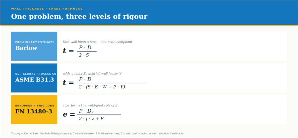
Each method addresses the same hoop stress balance with a differing degree of rigor. Barlow reduces the calculation to basic geometry. ASME B31.3 and EN 13480-3 introduce the correct factors required to convert an approximate figure into a defensible engineering value.
| Method | Equation | Use case |
| Barlow | t = (P x D) / (2 x S) | Thin-wall estimation only. Not code-compliant on its own |
| ASME B31.3 | t = (P x D) / (2 x (S x E x W + P x Y)) | US and global process piping code design |
| EN 13480-3 | e = (P x D_o) / (2 x f x z + P) | European industrial piping equivalent |
- P denotes internal design pressure
- D or D_o represents the pipe outside diameter
- S or f indicates allowable stress at design temperature
- E is the quality factor, valued at 1.0 for seamless pipe
- W, the weld strength reduction factor, likewise remains 1.0 for seamless products below 950°F
- Y, the wall factor, is fixed at 0.4 for austenitic and ferritic steel below 900°F (482°C)
- z performs the equivalent function to E within the European standard, representing the weld joint coefficient, set at 1.0 for seamless pipe.
Barlow’s Formula
Barlow’s equation derives directly from a thin-wall hoop stress balance. The method excludes quality factor, weld reduction term, wall factor, corrosion allowance, and mill tolerance in their entirety, which accounts for its continued use as a rapid preliminary check. For thin-wall austenitic pipe, the resulting figure approximates the code-derived value closely. As the wall thickness increases, that agreement diminishes considerably. Barlow’s formula remains appropriate for preliminary estimation. It shouldn’t be presented as a code-compliant wall thickness in any formal specification.
ASME B31.3 Design Equation
ASME B31.3 governs process piping design throughout the United States, the Middle East, and much of Asia. The standard extends Barlow’s approach through three corrections of material consequence. The quality factor E is assigned a value of 1.0 for seamless pipe under Table A-1B. The weld reduction factor W similarly remains at 1.0 for seamless products within the lower temperature range. The Y factor, fixed at 0.4 for austenitic and ferritic steel below 900°F, represents the term most frequently omitted in preliminary calculations, and its inclusion materially affects the denominator at elevated pressures. Allowable stress S is obtained from ASME B31.3 Table A-1 and varies according to both alloy and design temperature. Following the calculation of t, the engineer adds a corrosion allowance and divides the result by the mill tolerance factor, typically 0.875 for a 12.5 % tolerance, to establish the wall thickness specified for procurement.
EN 13480 Design Equation
EN 13480 serves as the European equivalent, governing the majority of projects across the European Union and additional projects elsewhere by client specification. For thin-wall pipe, the two equations produce results in close agreement. Divergence appears only at higher pressures and greater wall thicknesses, where the structure of the correction terms differs slightly between the two standards. Allowable stress f is obtained from EN 13480-3 Annex E rather than the corresponding ASME table, a distinction that prevents the two codes from arriving at identical figures even for identical geometry. The weld joint coefficient z performs the same function as ASME’s E factor, remaining at 1.0 for seamless pipe and decreasing for welded products depending on joint type and inspection level.
Worked Example: 6-inch SCH 80 316L at 400°F and 1000 psi
A complete calculation demonstrates the precise contribution of each factor. Design pressure is set at 1000 psi (6.9 MPa), with a pipe outside diameter of 6.625 in (168.3 mm) for 6-inch NPS.
| Step | Value |
| Design pressure P | 1000 psi (6.9 MPa) |
| Pipe outside diameter D | 6.625 in (168.3 mm) |
| Allowable stress S (316L at 400°F, approximate) | 16,400 psi (113 MPa) |
| Quality factor E (seamless) | 1.0 |
| Weld factor W | 1.0 |
| Y factor (austenitic below 900°F) | 0.4 |
| Barlow result | t = 0.202 in (5.13 mm) |
| ASME B31.3 result | t = 0.197 in (5.00 mm) |
| Plus corrosion allowance 0.0625 in, mill tolerance 0.875 | t_order = 0.297 in |
| SCH 80 actual wall (B36.19M) | 0.432 in |
| Verdict | SCH 80 exceeds the calculated requirement with a substantial margin |
The ASME B31.3 arithmetic proceeds as follows: 1000 x 6.625 = 6,625. The denominator resolves to 2 x (16,400 + 400) = 33,600. Division yields t = 6,625 / 33,600 = 0.197 in. After adding the corrosion allowance and applying the mill tolerance factor, the required specified wall thickness is 0.297 in, well below the 0.432 in provided by SCH 80 pipe.
Allowable Stress Is Where Material Choice Changes the Answer
In an alloy comparison, pipe size and pressure stay the same. Allowable stress changes, and that single factor can determine whether a project specifies 304L or a higher-performance grade.
| Alloy (UNS) | Allowable stress at 400°F (ksi) | Allowable stress at 400°F (MPa) |
| 304L (S30403) | 13.7 | 94 |
| 316L (S31603) | 16.4 | 113 |
| 22Cr duplex (S32205) | 24 | 165 |
| S32750 seamless pipe | 31 | 214 |
| Inconel 625 pipe | 37 | 255 |
A super-duplex wall calculates at approximately half the thickness required for 316L under identical pressure and diameter. This difference underlies the lifecycle cost argument for higher-alloy grades: reduced material mass, reduced weld volume, and reduced structural load across supports and connecting flanges.
Burst Pressure vs Design Pressure
Burst pressure estimation applies the Barlow form with ultimate tensile strength substituted for allowable stress: P_burst ≈ (2 x UTS x t) / D. This figure holds genuine value for sanity checks, failure analysis, and safety-margin reporting to management, though it holds no place within a formal design package. Code-specified design pressure incorporates a defined safety margin against both yield and rupture, typically three to four times the ultimate tensile strength, depending on service classification, and substituting burst pressure for that margin undermines the purpose of the design calculation entirely.

Use Our Burst Pressure Calculator
The burst pressure calculator accepts pipe outside diameter, wall thickness, alloy, and design temperature as inputs, returning the ASME B31.3 design pressure alongside a Barlow burst estimate without delay. The tool supports two distinct workflows: verification of a specification prior to purchase order issuance, and assessment of existing piping against its actual chemistry during field investigation. No online calculator, including this one, replaces formal stress engineering for cyclic, fatigue, or creep service. It addresses the preliminary question. The governing engineering decisions remain the responsibility of a qualified engineer with a complete loading history available.
Conclusion
Barlow’s formula serves as a preliminary estimation. ASME B31.3 and EN 13480 govern the final drawing, and neither should be substituted for a napkin calculation regardless of project urgency. Allowable stress, rather than the formula itself, is the variable that changes materially with alloy selection, as the comparison table demonstrates. Verify any preliminary figure using the free burst pressure calculator before finalizing a specification. Xintongda Special Steel supplies seamless pipe across every grade discussed in this article to exact wall specification, with EN 10204 3.1 or 3.2 certification issued from its mill in Songyang, Zhejiang.